
Installation Sheet
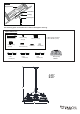

1. Rod Connections:
a. Thread the fixture wire from the fixture through the lower rod, then
secure the lower rod onto fixture using the threaded pipe.
b. Thread the fixture wire through the middle rod, and then secure the
middle rod onto the lower rod using the threaded pipe.
c. Thread the fixture wire through the upper rod, and then secure the
upper rod onto the middle rod using the threaded pipe.
Note: Length adjustable fr
om 20" to 62". Use fewer
rods if shorter length is desired.
2.
Thread the fixture wire through the canopy kit, then secure the rod
assembly to the set nipple of the canopy kit.
3. Attach the mounting strap to outlet box by using two mounting screws.
4. Pull out the source wires from the outlet box. Make wire connections
using wire connectors as follows:
---Connect the smooth-coated wire (marked) from the fixture
to the black wire from the power source.
---Connect the ribbed-coated wire (unmarked) from the
fixture to the white wire from the power source.
---Attach the fixture grounding wire to the mounting
strap with the green grounding screw. Then
connect it to the house grounding wire with a
wire connector.
Carefully put the wires back into the outlet box.
5. Attach the canopy kit to the mounting strap by
inserting the fixture mounting screws, then secure it with two bolt nuts.
6. Attach the glass shade onto the fixture, secure it with a socket ring.
7. Install bulb (not included). See relamping label at socket area or
packaging for maximum allowed wattage.
8. Angled mounting recommended for a vaulted or angled ceiling. (See Fig. 1)
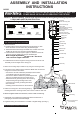
ASSEMBLY AND INSTALLATION
INSTRUCTIONS
NOTES: 1. Before installing, consult local electrical codes for wiring and grounding requirements.
2. READ AND SAVE THIS INSTRUCTION.
H0220
181206
WARNING:
TO AVOID RISK OF ELECTRICAL SHOCK, BE SURE TO SHUT OFF
POWER WHILE INSTALLING OR SERVICING THIS FIXTURE.
Hardware Package (included):
Turn off the power at fuse or circuit box.
Installation Steps
Mounting Screw (C)
Lock Nut (F)
Wire Connector (E)
Mounting Strap (A)
Fixture Mounting
Screw (D)
Green Grounding
Screw (B)
Canopy Kit
Outlet Box
House Grounding Wire
Wire Connector (E)
Lock Nut(F)
Mounting Strap (A)
Green Grounding Screw (B)
Mounting Screw (C)
Upper Rod
Upper Rod
Middle Rod
Lower Rod
Fixture body
Threaded Pipe
Threaded Pipe
Threaded Pipe
Fixture Wire
Fixture Mounting Screw(D)
Fixture Grounding Wire
Set Nipple
Bolt Nut(G)
Bolt Nut(G)
Turn on the power at fuse or circuit box.
Fixture
Bulb Type A Max.60W
(not included)
Socket Ring
Glass Shade