
User Manual
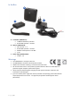
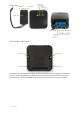
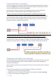
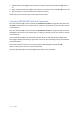
Table Of Contents

P a g e | 8
Connecting a Device to the Relays
Connect your device to the receiver by using the NO (normal open) & COM (common) terminals of
each channel (10 & 11) for standard off-mode. If you prefer standard on-mode, please use the NC
(normal closed) & COM (common) terminals (10 & 11).
Please note that the relays are suited for max. 48 VDC operation on 5A (resistive load) each.
Both channels are dry contacts (power needs to be supplied by another source).
Example 1: device with the same power supply voltage as the VM130V2SET with NC contacts
12 V LED strip connected to channel 1 on the NC (normally closed) and COM (common) terminals.
The LED strip shares the power supply voltage of the power supply unit with the VM130V2SET.
When connecting the schematic below, the LED strip will burn as long as channel 1 is off. When
switching on channel 1 the LED strip will switch off.
Example 2: device with different power supply voltage as the VM130V2SET with NO contacts
24 V LED strip connected to channel 2 on the NO (normally closed) and COM (common) terminals.
The LED strip has its own power supply source. When connecting the schematic below, the LED strip
will not burn as long as channel 2 is off. When switching on channel 2 the LED strip will switch on.
Generating a new Code for the Transmitter
Simultaneously hold the CH1 button (2) and CH2 button (3) on the transmitter for at least 5 seconds.
The new code will be generated. After successful completion, the red indicator LED (4) on the
transmitter will flash briefly.
Please note that you will need to re-pair the transmitter with the receiver after generating a new code for
the transmitter.
Clearing Transmitters from the Receiver Memory (Reset)
1. Power off the receiver by disconnecting the power.
2. Make sure there are no connections to the receiver on CH1 RELAY and CH2 RELAY (10 & 11).
3. Power on the receiver by connecting the power.