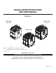
INSTALLATION INSTRUCTIONS AND USER MANUAL MODELS HRV 2600* HR 2.6* HEPA 3100* HF 3.1* HEPA 4100* VB0064 NOTES: 1. HRV 2600* model is available in Canada only. 2. HEPA 4100* model is available in United States only. *Patents pending RESIDENTIAL USE ONLY READ AND SAVE THESE INSTRUCTIONS INSTALLER: LEAVE THIS MANUAL WITH THE HOMEOWNER. HOMEOWNER: USE AND CARE INFORMATION ON PAGES 18 TO 21. 04313 rev.
ABOUT THIS MANUAL First, we want to congratulate you on your purchase of this excellent unit which will allow you and your family to enjoy clean and healthy air throughout your home for years to come! Because of the large amount of models covered by this publication, the illustrations are typical ones. Some details of your unit may be slightly different than the ones shown.
TABLE OF CONTENTS 1. TYPICAL INSTALLATIONS . . . . . . . . . . . . . . . . . . . . . . . . . . . . . . . . . . . . . . . . . . . . . . . . . .4-6 1.1 HRV 2600, HR 2.6, HEPA 3100, HF 3.1 AND HEPA 4100 UNIT INSTALLATIONS . . . . . . . . . . . . . . . . . . 4 1.1.1 STAND ALONE . . . . . . . . . . . . . . . . . . . . . . . . . . . . . . . . . . . . . . . . . . . . . . . . . . . . . . . . . . . . . . . .4 1.1.2 CENTRAL DRAW POINT . . . . . . . . . . . . . . . . . . . . . . . . . . . . . . . . . . . . . . . . . .
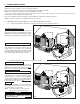
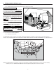
1. TYPICAL INSTALLATIONS Installations may vary according to the model number and the position in which the unit is installed. Use the following illustrations as guidelines to help you decide on how your unit will be installed. All the units should be hung from the joists, and installed either vertically or horizontally. NOTE: For more details, see Point 5.2 in Section 5 INSTALL THE UNIT. In every case, bathroom fans and a range hood should be used to exhaust stale air.
1. TYPICAL INSTALLATIONS (CONT’D) 1.1 HRV 2600, HR 2.6, HEPA 3100, HF 3.1 AND HEPA 4100 UNIT INSTALLATIONS (CONT’D) 1.1.3 RETURN-TO-RETURN INSTALLATION (CONNECTION TO HRV 2600 AND HR 2.6 A FORCED AIR SYSTEM) UNITS ONLY Stale air is exhausted to the outside. Outside fresh air is filtered and supplied to the return (plenum) of the forced air unit. See figure at right. HEPA 3100, HF 3.1 AND HEPA 4100 UNITS ONLY A portion of stale air is exhausted to the outside and the rest is drawn to the unit.
1. TYPICAL INSTALLATIONS (CONT’D) 1.2 INSTALLATION FOR HEPA 4100 ONLY (CONT’D) 1.2.2 HEPA 4100 ATTIC INSTALLATION All 3 types of installations can be used in the attic (Stand Alone, Central Draw Point or Return-Return). The example shown below is a Return-Return installation (connection to a forced air system). CAUTION Due to the potential temperature difference between the attic and the rest of the house, all unit ducts must be insulated. CAUTION The attic temperature must always be above 0°C (32°F).
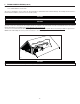
2. DIMENSIONS 2.1 HRV 2600 AND HR 2.6 UNITS 2.2 HEPA 3100, HF 3.1 AND HEPA 4100 UNITS 29.4'' (748 mm) 30.2'' (767 mm) 17.8'' (452 mm) 17.8'' (452 mm) 22.9'' (581 mm) 22.9'' (581 mm) VK0048A VK0049A FRONT VIEW 2.3 MOUNTING • AND FRONT VIEW TOP VIEW TOP VIEW SERVICING CONSIDERATIONS The two following pictures are showing the minimum clearance needed to open the door completely. 8” (203 mm) 22” (559 mm) 22.5” (572 mm) 15.
3. BEFORE STARTING 3.1 INSPECT THE CONTENTS OF THE BOX ! WARNING To avoid risk of suffocation, discard the plastic bag wrapping the unit and the wall control. • Inspect the exterior of the unit for shipping damage. Ensure that there is no damage to the door, door latches, main switch, etc. • Inspect the interior of the unit for damage. Ensure that blower assembly, heat recovery core, insulation, dampers, MERV8 filter (HRV 2600 or HR 2.6 units only) prefilter and HEPA filter (HEPA 3100, HF 3.
4. WALL CONTROL INSTALLATION ! WARNING Always disconnect the unit before making any connections. Failure in disconnecting power could result in electric shock or damage of the wall control or electronic module inside the unit. CAUTION Failure to comply with the following can cause erratic operation of the unit: • Never install more than one optional wall control per unit.
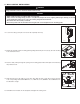
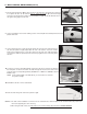
4. WALL CONTROL INSTALLATION (CONT’D) A 7. Turn the unit switch knob to OFF position in order to unlock the door. Unlatch the door and open it. If required, the door can be removed. To do so, remove the stopper (A) located on the right side of the door hinge. Then, hold the door and hit with your palm its left side. Slide the door to the right to disengage it from the unit. VD0170 8. Using a screwdriver, remove the 2 retaining screws of the front plate and carefully remove the front plate from the unit.
5. INSTALL THE UNIT 5.1 MOUNT THE PORTS ON THE UNIT Mount the 8” oval ports and the 5” to 6” oval ports on the top of the unit using the screws provided in the hardware box (4 screws no. 8 x 3/4” long per port). See figure at right. NOTE: All ports of the HRV 2600 and HR 2.6 are 5” to 6” oval. VO0018 5.2 HOW TO HANG THE UNIT Use the 4 chains and springs in the hardware pack provided with the unit. According to your needs, you can install the unit either in vertical or horizontal position.
5. INSTALL THE UNIT (CONT’D) 5.3 PLANNING OF THE DUCTWORK All units in this manual are prebalanced. • Keep it simple. Plan for a minimum of bends and joints. • Keep the length of outside insulated duct to a minimum. • Do not ventilate crawl spaces or cold rooms. Do not attempt to recover the exhaust air from a dryer or a range hood. This would cause clogging of the filters and recovery module.
5. INSTALL THE UNIT (CONT’D) 5.4 INSTALLING NON-INSULATED DUCTS 5.4.1 STAND ALONE SYSTEM (AS AND REGISTERS (CONT’D) ILLUSTRATED IN SECTION 1.1.1) (CONT’D) ALL UNITS How to connect the flexible duct to the unit ports • Using the colored sticker dot included, identify which duct it is (red dot for stale airflow and blue dot for filtered airflow). Repeat the procedure for the other register (or diffuser). (No dots for HRV 2600 and HR 2.6 units.
5. INSTALL THE UNIT (CONT’D) 5.4 INSTALLING NON-INSULATED DUCTS AND REGISTERS (CONT’D) 5.4.2 CENTRAL DRAW POINT (AS ILLUSTRATED IN SECTION 1.1.2) (CONT’D) Fresh/Filtered air ductwork (Return side connection) (cont’d) HEPA 3100, HF 3.1 AND HEPA 4100 UNITS ONLY (CONT’D) • Fix the duct connector to the forced air unit duct using its 4 retaining screws (no. 8 x 3/4” long). Seal with duct tape. • Take one end of the 8’’ flexible duct and slide it over the duct connector. Secure with a tie wrap.
5. INSTALL THE UNIT (CONT’D) 5.5 INSTALLING INSULATED FLEXIBLE DUCTS CAUTION Make sure the vapor barrier on the insulated ducts does not tear during installation. Use the following procedure for connecting the insulated flexible ducts to the Tandem® transition* (EXHAUST AIR TO OUTSIDE and FRESH AIR FROM OUTSIDE). NOTE: If the joists are perpendicular to the ducts, or if the connection to the exterior hood is in a limited area, your installation will need two exterior hoods instead of one.
5. INSTALL THE UNIT (CONT’D) 5.5 INSTALLING INSULATED FLEXIBLE DUCTS (CONT’D) 5.5.2 CONNECTION TO THE 5’’ TO 6’’ OVAL PORTS OF THE UNIT (CONT’D) CAUTION Avoid compressing the insulation when you pull the tape tightly around the joint. Compressed insulation loses its insulation properties and causes water dripping due to condensation on the exterior surface of the duct. BACK OF THE UNIT 4. Apply duct tape gently to the joint in order to make an airtight seal. 5.
5. INSTALL THE UNIT (CONT’D) 5.6 INSTALLING DUAL EXTERIOR HOOD (CONT’D) 5.6.3 CONNECTING TANDEM® TRANSITION TO EXTERIOR DUAL HOOD (CONT’D) Xmas tree pin 2. Join the end of the Tandem transition to the rear of the exterior backplate. Secure with 2 Xmas tree pins and seal properly with duct tape. VD0085 CAUTION The exterior backplate must be installed with the word “TOP’’ pointing upward. 3. Lean the exterior backplate to the exterior wall. Using 4 no. 8 x 1½” screws, fix it to the wall.
6. CONTROLS 6.1 MAIN SWITCH All units are equipped with a 3-position main switch, located on the front panel. NORMAL/REMOTE: UNIT IS OPERATING ON NORMAL SPEED. THIS IS THE RIGHT POSITION WHEN A WALL CONTROL OFF: UNIT IS USED. IS OFF AND DOOR IS BOOST: UNIT IS OPERATING ON HIGH SPEED. UNLOCKED. VC0053 6.2 40415 AND 40425 WALL CONTROLS DESCRIPTION The included wall control is 40415 (intented for HRV 2600, HEPA 3100 and HEPA 4100 units only) or 40425 control (intented for HR 2.6 and HF 3.
6. CONTROLS (CONT’D) 6.4 WALL CONTROLS CONFIGURATION See the configuration table below for the list of configuration parameters. Press the Menu button for 3 seconds to enter or exit the configuration menu. NOTE: The wall control automatically saves any changes and exits the configuration menu if no button is pressed within the next 60 seconds. Press the Menu button briefly to advance to the next parameter (menu number). Press the or button to change the parameter setting.
7. MAINTENANCE ! WARNING Risk of electric shocks. Before performing any maintenance or servicing, always disconnect the unit from its power source. 7.1 BIANNUAL MAINTENANCE (ESSENTIAL) Perform this maintenance when the Filter Maintenance LED is flashing. Follow these steps: 1. Turn switch knob to OFF to unlock the door. 2. Unlatch the door and open it. Clean the inner side of the door with a clean damp cloth, them wipe with a dry one. 3. Slide out the heat recovery core (HRV 2600, HR 2.
7. MAINTENANCE (CONT’D) 7.1 BIANNUAL MAINTENANCE (ESSENTIAL) (CONT’D) 1 1 6. Wash the 2 core filters under hot water with mild soap. Rinse thoroughly and let dry completely before reinstalling on the core. Remove the dust on the core using a vacuum cleaner with a soft brush attachment. 2 VD0091 1) Core filters 2) Core NOTE: Make sure the damper spring (1) is still inside the left front port opening before reinstalling the heat or energy recovery core. 1 VD0120 1) Damper spring 7.
8. PARTS ORDERING CHART No. 1 2 3 4 5A 5B 6 7A 7B Description Prefilter Kit (2) HEPA Filter Kit Pleated MERV 12 Filter Kit* Washable Foam Filter MERV 8 Core Filter Kit (2) Core Filter Kit (2) Single Exterior Hood Kit** Wall Control 40415 Wall Control 40425 Part no. HRV 2600 05123 04803 1* 04804 1* 04852 1 05120 1 05689 13940 1 40415 1 40425 - HR 2.6 1* 1* 1* 1 1 1 HEPA 3100 1 1 1* 1* 1 1 1 - HF 3.1 HEPA 4100 1 1 1 1 1* 1* 1* 1* 1 1 1 1 1 1 - *The HEPA filter is factory installed in HEPA 3100, HF 3.