
User manual


- 9 -
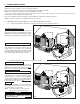
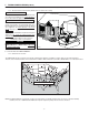
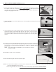
1. Route the cable from the unit to a convenient location for the wall control.
2. Loosen the locking screw (the screw cannot be completely removed).
3. Detach the faceplate from the mounting plate by pulling the bottom part. If necessary, bore the mounting
holes and insert anchors.
4. Pass the cable (4 wires) through the opening of the mounting plate and mount the plate to the wall using
the provided screws.
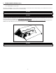
5. Splice back the end of the cable to access the 4 wires. Strip the end of each wire. Connect each wire
to its corresponding terminal: YELLOW wire to “Y’’, RED wire to “R’’, GREEN to “G’’ and BLACK to “B’’.
See illustration at right.
6. Reinstall the front module onto the back plate and tighten the locking screw.
CAUTION
Failure to comply with the following can cause erratic operation of the unit:
• Never install more than one optional wall control per unit.
• Keep control low voltage wiring at least 1 foot (305 mm) away from motors, lighting ballast, light dimming circuit and
power distribution panel. Do not route control wiring alongside electrical wires.
• Ensure the wires are securely connected.
• Disconnect power from the unit before removing the wall control faceplate from its mounting plate.
WARNING
Always disconnect the unit before making any connections. Failure in disconnecting power could result in electric shock or
damage of the wall control or electronic module inside the unit.
!
4. WALL CONTROL INSTALLATION
VC0095
VC0096
VC0097
VE0157
BLACK
wire
YELLOW
wire
GREEN
wire
RED
wire