HRV Vertical Unit Ventilators Classroom Ventilators with Energy Recovery Installation, Operation and Maintenance Instructions Manual Capacity: Up to 1,400 cfm Model: HRV450w, HRV1000w ©2012 Venmar CES Inc.
Table of Contents Nomenclature.......................................................................................................................................................................3 Safety Considerations..........................................................................................................................................................5 Specifications..........................................................................................................................
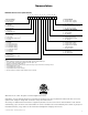
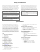
Nomenclature HRV450w Nomenclature (300–800 cfm) 1 2 3 4 5 6 7 8 9 10 11 1. FROST CONTROL D – Recirc defrost1 N – Non-defrost 2. VOLTAGE A – 120/1/602 B – 208/120/1/603 C – 230/120/1/603 3. ENERGY RECOVERY P – Poly core A – Aluminum core 4. HEATING E – Electric heat H – Hot water2 P – Proportional electric heat4 X – No heat2 5. HEATING CAPACITY 0 – No heat5 1 – 2.5 kW (one-stage)6 2 – 5.0 kW (one-stage)6 3 – 5.0 kW (two-stage)6 4 – 7.5 kW (two-stage)6 5 – 10.
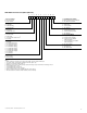
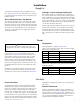
HRV1000w Nomenclature (400–1,400 cfm) 1 2 3 4 5 6 7 8 9 10 11 1. FROST CONTROL D – Recirc defrost1 N – Non-defrost 11. EXTERNAL DISCONNECT N – Non-fused disconnect switch9 X – No disconnect switch 2. VOLTAGE A – 120/1/602 B – 208/120/1/603 C – 230/120/1/603 10. EXHAUST AIR DAMPER 1 – Motorized 2 – Spring return 3 – No damper 9. OUTSIDE AIR DAMPER 1 – Insulated motorized 2 – Insulated spring return 3 – No damper 3. ENERGY RECOVERY P – Poly core A – Aluminum core 4.
Safety Considerations Warning, Caution and Important notes appear throughout this manual in specific and appropriate locations to alert Installing Contractors, maintenance or service personnel of potential safety hazards, possible equipment damage or to alert personnel of special procedures or instructions that must be followed as outlined below. WARNING ! Identifies an instruction which, if not followed, might cause serious personal injuries including possibility of death.
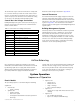
Installation Rough In Drainage – Heat Exchanger/Cooling Coil The wallmount ventilators must be installed on a level base. Refer to Appendix A for dimensions. Zero clearance is required between the bottom of the unit and any combustible material. Units equipped with air conditioning have a condensate line connected at the top of the unit which drains into the main condensate line. The heat exchanger and cooling coil drain must be fitted through the bottom of the case.
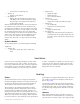
The thermostat may be remote mounted on a nearby wall. If it is remote mounted, control wire leads must be fitted into the case through a sealed strain relief clamp where required. If a proper seal cannot be achieved with the clamp, use silicone or an equivalent water/air-tight sealant. Detailed control wiring is illustrated in Appendix D. Internal Thermostat Building Management System connections will vary by application. All control connections to the external thermostat are 24 VAC 60 Hz.
–– Connection for condensing unit Signal to S1 –– Engage occupied mode • No signal to S1 –– Engage unoccupied mode (fans off) and close vent damper. On a call for heat/cool the supply fan runs only in recirculation mode (with frost control option installed). With the thermostat and sub-base, connect terminal G on the sub-base to the terminal ‘G’ in the control box.
Figure A4. Control valve is to be hooked up to a remote duct stat supplied by others (optional connection to ‘W1’ on the sub-base). All wiring is low voltage. This operation is single-stage and on a second stage call for heat the sup- ply fan will go to high speed, the exhaust fan will shut off, and the unit will go into recirc mode. See Appendix A, Figure A2 and Figure A4 for more details. High Temperature Limit Control IMPORTANT Electric models only.
Recirculation Control In the HRV450w ventilation mode, the ventilation damper is open and the supply air is 100% outdoor air. In the HRV1000w ventilation mode, the ventilation damper is open and the supply air is a mixture with a percentage of return air (see Table B2 or Table B3). plenum. Units equipped with recirculation control are built with a damper mechanism controlling airflow through the intake duct. Ventilation mode is activated by a signal to terminal S1.
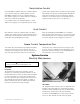
! WARNING Disconnect power before maintaining the unit. Figure 3: HRV1000w exhaust filter Figure 2: HRV1000w exhaust filter Annual Maintenance Drain Pans and Interior of Unit The inside of the unit, including drain pans (if equipped), should be wiped clean annually with a soft cloth and mild cleaning solution. Check the drain fittings (if equipped) to ensure they are draining freely.
! WARNING Disconnect power before maintaining the unit.
VCES-VUV-IOM-1A – HRV450w & HRV1000w Outdoor air Exhausr air Return air 94.00” [2388] Supply air LEFT VIEW Return Collector Base (optional) Top supply plenum (optional) 20.50” [521] 5.00” [127] Filter Return air A 2” [51] space must be left between the right side of the unit and any obstruction to allow airflow. Recirculation opening for units with cooling. Supply air 24.00” x 6.00” [610 x 153] Double deflection grille 8.00” [203] 24.00” x 6.
Figure A2: HRV450w coil dimensions VCES-VUV-IOM-1A – HRV450w & HRV1000w 14 65.00” [1,651] 3.50” [89] 4.50” [114] 11.00” [279] 11.00” [279] Supply air opening FRONT VIEW C 1.63” [41] Note: Dimensions in [ ] are millimeters. 2.25” [57] A 12.00” [305] B 2.88” [73] 2.50” [64] 2.81” [71] 2.38” [60] 3.13” [80] 13.
Figure A3: HRV1000w unit dimensions VCES-VUV-IOM-1A – HRV450w & HRV1000w 15 Outdoor air Exhaust air LEFT VIEW 21.00” [533] Return air 92.50” [2350] Supply air Filter Control box 8.00” [203] FRONT VIEW 41.00” [1,041] 6.00” [152] Supply air opening 20.00” [508] Fixed grille @ 45º RIGHT VIEW 36.00” x 6.00” [914 x 153] Return air Supply air Double deflection grille 24.00” x 6.00” [610 x 153] 7.00” [178] 3.00” [76] 3.50” [89] 2.00” [51] TOP VIEW WITH DUCTED SUPPLY PLENUM 8.
Figure A4: HRV1000w coil dimensions VCES-VUV-IOM-1A – HRV450w & HRV1000w 16 1.00” [25] 3.38” [86] B 20.00” [508] 4.50” [114] A 1.75” [44] 68.00” [1,727] Outdoor air Exhaust air 2.25” [57] C RIGHT VIEW 16.63” [422] 18.50” [470] 1.19” [30] Supply air opening 3.00” [76] TOP VIEW WITHOUT SUPPLY PLENUM Note: Dimensions in [ ] are millimeters. C B A Connection Table Connection Sizes Field power supply outlet 1¼” Coil connection ½” (sweat) Coil connection ½” (sweat) HYDRONIC HEAT 4.
Appendix B: Ventilation and Airflow Information Table B1: HRV450w Ventilation ESP (in. w.g.) 0.00 Polypropylene Core Low Speed 460 Polypropylene Core High Speed 685 Aluminum Core Low Speed 460 Aluminum Core High Speed 710 Recirc. Open for Dx Cooling 800 0.10 435 630 445 665 750 0.15 415 600 435 640 725 0.20 400 580 425 605 705 0.25 380 550 410 585 675 0.30 365 510 390 555 645 0.35 340 480 375 540 605 0.40 305 435 355 495 570 0.45 280 410 335 460 530 0.
Table B2: HRV1000w Reduced Low Speed Airflow Information Position of Recirc Panel Supply ESP Fan (in. w.g.) 0.00 0.10 Speed 3 Speed 4 Fully Closed TA (CFM) — TA (CFM) — OA (CFM) — TA (CFM) — OA (CFM) — TA (CFM) — OA (CFM) — TA (CFM) — OA (CFM) — TA (CFM) — OA (CFM) — 765 815 680 — — — — — — — — 1 2 3 4 Fully Open 0.20 715 795 670 845 615 865 595 860 495 865 485 0.30 660 765 650 835 610 845 585 815 490 845 475 0.
Table B3: HRV1000w High Speed and Regular Low Speed Airflow Information Position of Recirc Panel Supply ESP Fan (in. w.g.) 0.00 0.10 Speed 2 Speed 3 Speed 4 Fully Closed TA (CFM) 1,000 TA (CFM) 1,190 OA (CFM) 855 TA (CFM) 1,305 OA (CFM) 820 TA (CFM) 1,390 OA (CFM) 790 TA (CFM) 1,455 OA (CFM) 760 TA (CFM) 1,500 OA (CFM) 745 940 1,135 815 1,255 795 1,330 770 1,410 740 1,445 720 1 2 3 4 Fully Open 0.20 880 1,090 805 1,190 770 1,270 740 1,350 420 1,375 705 0.
Appendix C: Electrical Data Table C1: 208 VAC HRV450w Electric Heat AC Option Amount of Heat MCA 2.5 kW 5.0 kW 7.5 kW 10.0 kW 20.6 35.6 50.8 65.8 MOP BTU/hr 25 40 60 70 1½ Ton kW 5.3 5.3 5.3 5.3 8,533 17,065 25,598 34,130 2 Ton BTU/hr 18,000 18,000 18,000 18,000 kW 7.0 7.0 7.0 7.0 BTU/hr 24,000 24,000 24,000 24,000 Table C2: 230 VAC HRV450w Electric Heat AC Option Amount of Heat MCA 2.5 kW 5.0 kW 7.5 kW 10.0 kW 19.3 32.8 46.4 60.0 MOP BTU/hr 20 35 50 60 1½ Ton kW 5.3 5.3 5.3 5.
Appendix D: Low Voltage and High Voltage Wiring FACTORY WIRING CONTROL BOX TERMINAL BLOCK FACTORY WIRING BLACK R BLACK WHITE C WHITE ORANGE W1 ORANGE RED W2 VIOLET YELLOW Y1 GREY Y2 YELLOW S1 BLUE VIOLET S2 C1 FL ORANGE BROWN FH RED GREEN G Figure D1: Connections to terminal block in control box N Ground L2 L1 L1 L2 N High voltage terminals Notes: 1. Fused disconnect switch supplied by Installer. 2. 208–230 VAC/120/1/60 requires a neutral wire to be run with L1 and L2.
Appendix E: Thermostat and Wiring Connections Thermostat Sub-base Setup Thermostat Setup Factory supplied thermostats and sub-bases are configured and ready for installation. Use this information to configure thermostats that are field supplied. See the manufacturer’s instruction manual for detailed instructions on how to program the following thermostat functions that must be set: 1. 2. 3. 4. 5. Install jumper wires across the following terminals; refer to Figure E1.
Appendix F: Internal Thermostat T675A Terminal screws (3) As the temperature of the controlled medium falls below the setpoint less differential, the T675A switch makes terminals R to B and energizes a normally closed solenoid valve to provide heat. In cooling applications, the T675A makes terminals R to W as the temperature rises above the set point, energizing cooling equipment. Figure F1 shows the operation of the T675A.
info@venmarces.com www.venmarces.com Venmar CES Inc. has a policy of continuous improvement and reserves the right to change design and specifications without notice. ©2012 Venmar CES Inc.