
Specifications

VCES-VUV-IOM-1A – HRV450w & HRV1000w
6
The wallmount ventilators must be installed on a level
base. Refer to Appendix A for dimensions. Zero clearance
is required between the bottom of the unit and any com-
bustible material.
Unit Installed without a Top Plenum
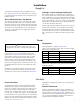
The supply air ducting must be connected to the supply
collar and constructed so there are no openings within
30” [762 mm] of the electric heating elements. Openings
within 30” [762 mm] of the elements must be fitted with
a permanent, non-removable protective screening. Zero
clearance is required between the supply duct and any
combustible material.
Drainage – Heat Exchanger/Cooling Coil
Units equipped with air conditioning have a condensate
line connected at the top of the unit which drains into the
main condensate line. The heat exchanger and cooling coil
drain must be fitted through the bottom of the case. Drain
connections within the case are accessible by removing the
bottom door. A length of PVC hose is supplied within the
case to make the drain connection.
A water trap must be provided in the drain line to prevent
back flow of sewer gases. This trap may be achieved by
looping the drain line. The drain must be installed in an
area in which it will not freeze. If the wallmount ventilator
has a collector base, the drain hose will be located in the
base.
A sealed strain relief clamp (supplied by the installer) must
be fitted into the case to accommodate a power line
connection (see Appendix A for knock out location). If a
sealed clamp cannot be used, the hole must be sealed
with silicone or an equivalent water/air-tight sealant.
Power must be connected to the unit through a fused
disconnect switch (to be supplied by the Installer). If the
unit has a top supply plenum, a hole for the power must
be field drilled in the plenum to accommodate the main
power in.
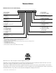
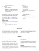
Terminals for line connection are located in the control
box within the wallmount ventilator and are labeled as
shown below. Connections are illustrated in Appendix D.
Single-phase
A wiring diagram is supplied in Appendix D.
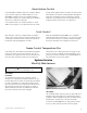
External Switches
The wallmount ventilator controls (optional with Build-
ing Management System), are located on the left side
panel. These controls consist of two rocker switches. The
switches are labeled ‘Ventilation Rate’ and ‘First Stage
Heating’. The ‘Ventilation Rate’ switch sets the fan speeds
to ‘Low’, ‘Off’, or ‘High’. This switch is activated through
terminal G and is also a system switch for an internal ther-
mostat. The ‘First Stage Heating’ switch engages or disen-
gages the function of the internal thermostat. On versions
with hydronic heating, there will be no ‘First Stage Heat-
ing’ switch.
External Thermostat
Heating, cooling and ventilation can be controlled by a
remote thermostat. The wiring configuration for the ther-
mostat subbase is shown in Appendix E. Ventilation may
otherwise be remote controlled by switching ‘R’ to ‘FL’ or
‘FH’. A separate information package on the subbase is
supplied with the wallmount ventilator.
Installation
Rough In
Power
Controls
WARNING
Ensure the power disconnect switch is off before con-
necting power to the unit or working with high voltage
lines.
!
Table 1: Line Connection to 208 VAC or 230 VAC, Single-
phase, 60 Hz for Electric Heat
L1 Hot Black
L2 Hot Red
N Neutral White
GND Ground Bare
L1 N 120 VAC 60 Hz
L2 L2 230 VAC 60 Hz or 208 VAC
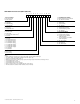
Table 2: Line Connection to 120 VAC 60 Hz Required for
Hydronic Heating
L1 Hot Black
N Neutral White
GND Ground Bare
L1 N 120 VAC 60 Hz