
Specifications

VCES-VUV-IOM-1A – HRV450w & HRV1000w
7
The thermostat may be remote mounted on a nearby wall.
If it is remote mounted, control wire leads must be fitted
into the case through a sealed strain relief clamp where re-
quired. If a proper seal cannot be achieved with the clamp,
use silicone or an equivalent water/air-tight sealant.
Control Box Low Voltage Connections
Building Management System connections will vary by ap-
plication. All control connections to the external thermo-
stat are 24 VAC 60 Hz.
Detailed control wiring is illustrated in Appendix D.
Internal Thermostat
An internal thermostat will engage Stage One when the
supply air temperature falls below its setpoint. The func-
tion of this thermostat is disabled when the external heat-
ing switch is set to ‘Off’. The operation of this thermostat
is given in Appendix F. This thermostat is not available
with the hydronic heating option or Building Management
System option.
Building Management Systems
Control operation of the wallmount ventilator by a Build-
ing Management System is available by connecting to
the terminals described above. For full control of the
wallmount ventilator by the management system, exter-
nal switches (if equipped) should be set to ‘Off’. External
switches set to ‘On’ will override the building manage-
ment control. Each operation is activated by switching
terminal ‘R’ to the corresponding terminal.
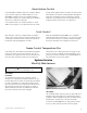
Once installed, the wallmount ventilator must operate
with balanced ventilation. Balanced ventilation is achieved
by obtaining equal rates of supply and exhaust airflow.
Airflow may be adjusted by balancing dampers (supplied
by Installer) within the supply and exhaust ductwork.
Systems that are not operating with balanced airflow will
not have effective energy recovery. Performance of the
heat recovery module will be reduced and freezing may
occur with cold outside air temperatures, resulting in
blockage of the heat recovery module.
Electric Models
The operating sequence is summarized by the following:
Signal from:
• Internal Stat
– Stage 1 heating
• Signal to W1
– Stage 2 heating
– Fans to low speed
– Send signal to baseboard contactors (optional in
field only)
• Signal to W2
– Supply fan on
– Exhaust fan off
– Stage 1 heating
– Close ventilation damper
• Signal to Y1
– Supply fan to ‘High’ and exhaust fan ‘Off’ (free
cooling)
• Signal to Y2
– Air conditioning (optional)
– Open recirc damper (HRV450w only)
Airflow Balancing
System Operation
Sequence of Operation
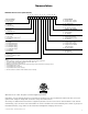
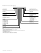
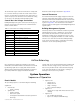
Table 3: Control Box Low Voltage Connections
Wire Color Connection and Description
Black R – 24 VAC Hot
White C – 24 VAC Common
Orange
W1 – Stage 1: Heating and signal for base-
board contactor (optional)
Red W2 – Stage 2: Heating and recirc
Yellow Y1 – Stage 1: Free cooling
Y2 – Stage 2: Dx Cooling (optional)
Violet S1 – Occupied mode
S2 – N/A
C1 – N/A
FL – Fans low speed
Brown FH – Fans high speed
Green G – Fans auto (low)