
Specifications
VCES-VUV-IOM-1A – HRV450w & HRV1000w
8
– Connection for condensing unit
• Signal to S1
– Engage occupied mode
• No signal to S1
– Engage unoccupied mode (fans off) and close
vent damper. On a call for heat/cool the supply
fan runs only in recirculation mode (with frost
control option installed).
With the thermostat and sub-base, connect terminal G on
the sub-base to the terminal ‘G’ in the control box. This
will enable the ventilation to run on occupied cycles when
the ventilation rate switch is on either ‘High’ or ‘Low’ and
the T7350 fan operation shows ‘On’ in the lower right
area of the display screen. When the fan operation shows
‘Auto’ only, a call for heat or cool will engage fan opera-
tion. Press the ‘Fan’ button on the T7350 to alternate
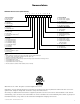
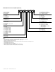
between ‘On’ and ‘Auto’. See Appendix E for the wiring
details.
Hydronic Models
The operating sequence is summarized by the following:
Signal from:
• Signal to W1
– Fans to low speed (duct stat to control zone
valve)
• Signal to W2
– Supply fan ‘High’
– Exhaust fan ‘Off’
– Close ventilation damper
• Signal to Y1
– Free cooling mode
– Supply fan on ‘High’ and exhaust fan ‘Off’
• Signal to Y2
– Air conditioning
– Connection for condensing unit
• Signal to S1
– Engage occupied mode
• No signal to S1
– Engage unoccupied mode (fans off) and close
vent damper (for units equipped with frost con-
trol). On a call for heat/cool the supply fan oper-
ates only.
Fan speed can be selected by setting the external ventila-
tion rate switch to ‘Low’, ‘Off’, or ‘High’. The fan opera-
tion on the T7350 must show ‘On’, in the lower right area
of the display screen, for continuous ventilation. If you do
not require ventilation, press the ‘Fan’ key to set the unit
to ‘Auto’. If ventilation is required, press the ‘Fan’ key to
set the unit to ‘On’. When the unit goes into the unoc-
cupied mode, the ventilation will shut down even if the
display shows the ‘On’ operation.
Electric
An internal thermostat acts as a supply air temperature
monitor and engages heating as necessary to preheat sup-
ply air before delivering it to the space being ventilated.
This thermostat comes with all electric heat models.
This thermostat is not available with hydronic heating.
The thermostat contacts R and B make a closure on tem-
perature fall which engages the heating contactor. The
thermostat is factory set at 59°F [15°C] (actual 55°F [13°C]
with differential set at two). For proper environment con-
ditions, the temperature of the supply air diffused should
be no lower than 55°F. This thermostat can be deactivated
by turning the first stage heating switch to the ‘Off’ posi-
tion. Further instructions for setting the thermostat are
given in Appendix F.
If no heating is required at all, then the first stage heat-
ing switch should be in the ‘Off’ position and the T7350
should display either ‘Off’ or ‘Cool’. During cooling sea-
son, the first stage heating switch should be in the ‘Off’
position.
Hydronic
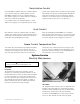
Units equipped with hot water heating coils will come
without controls for controlling flow, etc. Hot water pip-
ing connections are shown in Appendix A, Figure A2 and
Ventilation
Heating