
Specifications

VCES-VUV-IOM-1A – HRV450w & HRV1000w
9
Figure A4. Control valve is to be hooked up to a remote
duct stat supplied by others (optional connection to ‘W1’
on the sub-base). All wiring is low voltage. This operation
is single-stage and on a second stage call for heat the sup-
ply fan will go to high speed, the exhaust fan will shut off,
and the unit will go into recirc mode. See Appendix A, Fig-
ure A2 and Figure A4 for more details.
Temperature limit thermostats in the heating circuit will
break contact to the heating elements when the tempera-
ture rise across the heating elements becomes excessive.
This may be due to blocked filters, blocked energy recov-
ery module, blocked ducting, fan failure or fan relay fail-
ure. See the System Service section for proper equipment
maintenance.
First stage cooling puts the supply fan to high speed and
the exhaust fan shuts off.
Second stage cooling is an option and will call for Dx cool-
ing from a remote condensing unit. Both fans will run on
high speed.
Air conditioning is provided as an option. A field connec-
tion from ‘Y2’ on the terminal block (inside control box)
must be run to the contactor in the remote condensing
unit. This line will be 24 VAC hot. If a return line is also
required for the contactor, it can be taken from terminal
‘C’. See wiring diagram in control box for further details.
Suction and liquid line connections are made at the coil
(equipped with solder connects).
Holes in the top supply plenum are to be field drilled to
accommodate the refrigerant lines. On a call for cooling,
both fans will go to high speed and the recirc damper on
the right side of the unit will open to allow for increased
airflow over the coil.
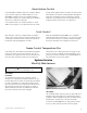
Air Conditioning Coil Installation
Place the provided insulation on top of the unit over the
matching supply opening. Place the coil and drain pan as-
sembly over the insulation and supply air opening. Place
clips in opposing corners of coil drain pan and fasten
down to the top of unit with screws. Leave enough clear-
ance around the back and side edges of the unit to allow
installation of the top supply discharge plenum or ducting
as required.
See Appendix A, Figure A2 and Figure A4 for installing the
air conditioning coil on top of the wallmount ventilator.
High Temperature Limit Control
First Stage Cooling
Second Stage Cooling – Air Conditioning
IMPORTANT
Electric models only.
WARNING
To prevent poor performance for air conditioning allow
4” to 6” [102 to 152 mm] from the right side to any wall
or partition.
!