
User`s manual

Wall Control 400-627-000-A 8/6/07 1/2
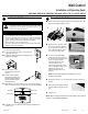
n Route the cable from the unit to a convenient
location for the wall control.
o Loosen the locking screw (the screw cannot be
completely removed).
p Detach the faceplate from the mounting plate by
pulling the bottom part.
q If necessary, bore the
mounting holes and insert
anchors.
r Pass the cable (4 wires)
through the opening of the
mounting plate and fix the
plate to the wall using the
screws provided.
s
Splice back the end of the cable to access the 4 wires. Strip the
end of each wire. Connect each wire to its corresponding terminal.
t Reinstall the front module onto the back plate and tighten the
locking screw.
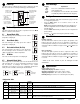
n Remove the front oval port (A) and the front panel (B) of the unit
by unscrewing their retaining screws.
o Splice back the end of the cable
to access the 4 wires. Strip the
end of each wire. Insert the end
of the cable through the small
hole on the front of the unit.
p To access the unit terminals,
remove the side door located on
the electrical box and punch out
its knock-out hole. Run the
cable through the hole and
connect each wire in its
corresponding terminal: yellow
wire to Y terminal, red wire to R
terminal, green wire to G
terminal and black wire to B
terminal.
NOTE: Push forward slightly on the little tabs (1) to ease
insertion of each wires.
q Reinstall the side door on the electrical box and the oval port on
the unit.
r Route the wire through its channel
and reinstall the front panel on the
unit.
s Plug the unit.
NOTE: When using the wall control, the main switch on the unit must
always be set to NORMAL/REMOTE.
n
Installing the Wall Control
1.
WARNING
Always disconnect power to the unit before making any
connections. Failure to disconnect power could result in
electrical shock or in damage of the wall control or of the
electronic module inside the unit.
CAUTION
Failure to comply with the following can cause erratic operation of the unit:
• Do not install more than one wall control per unit.
• Keep the low-voltage wires at least 1 foot (305 mm) away from
motors, lighting ballasts, light dimming circuits and electrical
panels. Do not route the wires alongside electrical wires.
• Ensure the wires are securely connected.
• Disconnect power from the unit before removing the wall control’s
faceplate from its mounting plate.
Red wire
Yellow wire
Green wire
Black wire
o
Connecting to the Unit
2.
A
B
1
Wall Control
Installation and Operating Guide
HEPA 3000 / HEPA 3100 / HRV 2500 / HRV 2600 / HF 3.0 / HF 3.1 / HR 2.5 / HR 2.6