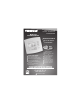
commercial SCHOOL THERMOSTAT T2900SCH Digital Thermostat PROGRAMMABLE up to 3-heat & 2-cool HEAT COOL Energy Saving Operation Morning Warm-up Period Programmable Override Unoccupied until button press Perfect for Classroom Operation Setpoint Limiting Security Separate Weekend/Weekday Programs 99 Days of Configuration Holiday Mode HEAT PUMP Soft Start Capability Back-Lit Display One for All Works with Virtually All Equipment Non-Volatile Memory Keypad Lockout 3 Security Levels Remote Sensor Ready 48
CAUTION Follow the Installation Instructions before proceeding. Set the thermostat mode to “OFF” prior to changing settings in setup or restoring Factory Defaults. CAUTION NEVER PUT MORE THAN ONE JUMPER ON THE SAME MISC JUMPER BLOCK! THIS MAY DAMAGE YOUR THERMOSTAT AND VOID YOUR WARRANTY. MISC3 MISC3 OK NOTE: Due to variations in environmental conditions, it is not always possible to achieve the desired humidification or dehumidification setpoint. This device complies with Part 15 of the FCC Rules.
How to Use This Manual The Table of Contents divides the thermostat features into sections making it easier to quickly find information. The first page of each section contains a more detailed list of the contents within that section, such as the example page shown below. SECTION 14 Timers and Deadbands Header shows section # and title of section Section 14 Contents: Adjusting the Heat/Cool Differential..............................14.2 Adjusting the Cycles Per Hour..................................14.
Glossary of Terms Auto-Changeover: A mode in which the thermostat will turn on the heating or cooling based on room temperature demand. Configurable Output Jumper: Using jumpers on the thermostat you can configure the MISC1, MISC2, and MISC3 terminals to control humidification, dehumidification, 2nd stage cooling, 3rd stage heating, and a programmable output. Cool Setpoint: The warmest temperature that the space should rise to before cooling is turned on (without regards to deadband).
Table of Contents 1 2 3 Basic Operation 4 Viewing Temperature 5 and Humidity Programming the 6 Daily Schedule Programming the 7 Fan Operation Thermostat Display 8 Options Humidification 9 Dehumidification 10 Viewing Equipment 11 Run-Times Electric Heat and 12 Heat Pump Operation Timers and Deadbands 13 Using the Programmable Output 14 Programming Remote 15 Sensor Operation Dry Contact Operation 16 Light Activated 17 Operation Override Timer 18 Operation Programming the Run19 Time Alerts Programming the 20 H
SECTION 1 Quick Start 1 Section 1 Contents: Setting the Clock and Day...........1.2 Selecting the Heat or Cool Mode............................................1.3 Selecting Your Desired Temperature................................1.4 Using the Fan Button...................1.4 Note: Following the instructions in this section will allow you to operate your thermostat using the factory default settings. These settings are depicted in the illustrations throughout this manual. Page 1.
MODE 1 HUMIDITY SET CLOCK Press the MODE and HUMIDITY buttons at the same time Setting the Clock I2:00 Am Setup During Setup & Programming: Pressing the UP or DOWN buttons will modify the flashing selection. I To adjust the Clock or Day use Press Setting the Day MODE Setup Mo Press the MODE and HUMIDITY buttons at the same time to return to normal operation. MODE 2 HUMIDITY SET CLOCK Page 1.2 Buttons.
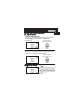
1 Selecting the Heat or Cool Mode Select Mode by Pressing the MODE Button Heating Only The HEAT setting indicates the temperature the room has to reach before the furnace will turn on to heat the room. Cooling Only The COOL setting indicates the temperature the room has to reach before the air conditioner will turn on to cool the room. Heating or Cooling AUTO will automatically select heat or cool based on room temperature demand.
Selecting Your Desired Temperature 1 (adjusting the setpoints) AUTO OR PROGRAM MODE Pressing the UP or DOWN buttons in Auto or Program mode will adjust both the heat and cool set temperatures simultaneously. I2:00 Su Adjust the desired set temperature with the 76 70 68 Pm COOL AUTO HEAT buttons. HEAT OR COOL MODE Pressing the UP or DOWN buttons in Heat or Cool mode will adjust only the heat or cool set temperature. I2:00 Su 70 Pm Adjust the desired set temperature with the 76 COOL buttons.
SECTION 2 Getting to Know Your Thermostat 2 Section 2 Contents: Front Panel Buttons.....................2.2 Display Features...........................2.3 Page 2.
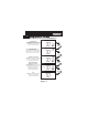
Front Panel Warmer Button (glows red) Backlit LCD Display I2:00 Pm Su 2 [ ] sometimes referred to as the UP button 74 COOL AUTO 72 HEAT Cooler Button (glows blue) Heat or Cool Demand Indicator Override Button Red = Heat, Green = Cool PLATINUM [ eries COMMERCIAL PROGRAMMABLE THERMOSTAT I2:00 74 Pm Su COOL AUTO 72 HEAT MODE HUMIDITY FAN PROGRAM HOLIDAY OVERRIDE SET CLOCK OUTDOOR QUICK RELEASE FOR ACCESSORY PORT (pg. 23.
Display Features 2 I8:88 88 I88 88 Am Program On Setup Pm StartStop HI SuMoTuWeThFrSa DeHumidify Service Filter Pan UV Light AUTO OFFON Unoccupied 123 Override FanOn COOL Outside Remote AUXHEAT LO Mode Indicators - Section 4 Selects the operational mode of the equipment. HEAT - Indicates the heating mode. COOL - Indicates the air conditioning mode. AUTO - Indicates the system will automatically changeover between heat and cool modes as the temperature varies.
Display Features 2 2 88 I8:88 I88 88 Am Program On Setup Pm StartStop HI SuMoTuWeThFrSa DeHumidify Service Filter Pan UV Light AUTO OFFON COOL Outside Remote AUXHEAT Unoccupied 123 Override FanOn LO Occupied & Unoccupied icons - Section 6 Indicates the program: Occupied or Unoccupied. Override icon - Section 6 Indicates the program is currently being overridden. Setup icon - Sections 7-20 Indicates the thermostat is in the setup mode.
Display Features 2 88 I8:88 I88 88 Am Program On Setup Pm StartStop HI SuMoTuWeThFrSa DeHumidify Service Filter Pan UV Light AUTO OFFON COOL Outside Remote AUXHEAT Unoccupied 123 Override FanOn LO UV Light icon - Section 11/19 Appears when the UV bulb should be serviced under normal conditions. Adjustable from 0 - 1950 days of operation. Remote icon - Page 22.4 Indicates the remote sensor reading of the thermostat is being viewed. AuxHeat icon - Pages 10.5 & 13.
SECTION 3 Setting the Clock and Day 3 Section 3 Contents: Setting the Clock..........................3.2 Setting the Day.............................3.2 Note: During setup & programming pressing the UP or DOWN buttons will modify the flashing selection. Page 3.
MODE HUMIDITY SET CLOCK Press the MODE and HUMIDITY buttons at the same time 3 Setting the Clock I2:00 Am Setup During Setup & Programming: Pressing the UP or DOWN buttons will modify the flashing selection. I To adjust the Clock or Day use Press Setting the Day MODE Setup Mo Press the MODE and HUMIDITY buttons at the same time to return to normal operation. MODE 2 HUMIDITY SET CLOCK Page 3.2 Buttons.
SECTION 4 Basic Operation 4 Section 4 Contents: Programming for Auto or Program Operation....................4.2 Selecting the Proper Operating Mode.........................4.3 Selecting Your Desired Temperature...............................4.7 Note: During setup & programming pressing the UP or DOWN buttons will modify the flashing selection. Page 4.
Programmable or Non-Programmable Thermostat 4 When the very simplest operation is desired, this thermostat may be configured to be non-programmable, with or without Auto-Changeover. Follow the step below. If ‘NO’ is selected, the thermostat will lockout the Program On screen; only the Off, Heat, Cool, and Auto screens may be accessed by pressing the MODE button. Select ‘YES’ if you would like your thermostat to be programmable, then the Program mode will be accessible through the use of the MODE button.
Manual or Auto-Changeover Thermostat When the very simplest operation is desired, this thermostat may be configured to be a manual heat and cool thermostat, with or without time period programmability. Follow the step below. 4 The thermostat may be programmed to function as a Heat Only or Cool Only thermostat by selecting ‘NO’ in the setup screen below. This will lockout the Auto-Changeover screen and only allow the Off, Heat, Cool, and Program On screens to be accessed.
Operating Mode when the Thermostat is Configured to be: 4 NON-PROGRAMMABLE WITH MANUAL-CHANGEOVER - If the thermostat is configured to be a non-programmable thermostat with Manual-Changeover, the following screens will be available by pressing the MODE button. Select the Mode by Pressing the MODE Button Heating Only The HEAT setting indicates the temperature the room has to reach before the furnace will turn on to heat the room.
Operating Mode when the Thermostat is Configured to be: NON-PROGRAMMABLE WITH AUTO-CHANGEOVER - If the thermostat is configured to be a non-programmable thermostat with Auto-Changeover, the following screens will be available by pressing the MODE button 4 Select the Mode by Pressing the MODE Button Heating Only The HEAT setting indicates the temperature the room has to reach before the furnace will turn on to heat the room.
Operating Mode when the Thermostat is Configured to be: PROGRAMMABLE WITH MANUAL-CHANGEOVER - If the thermostat is configured to be a programmable thermostat with Manual-Changeover, the 4 following screens will be available by pressing the MODE button. Select the Mode by Pressing the MODE Button Heating Only The HEAT setting indicates the temperature the room has to reach before the furnace will turn on to heat the room.
Operating Mode when the Thermostat is Configured to be: PROGRAMMABLE WITH AUTO-CHANGEOVER - If the thermostat is configured to be a programmable thermostat with Auto-Changeover, the following screens will be available by pressing the MODE button. 4 Select the Mode by Pressing the MODE Button Heating Only The HEAT setting indicates the temperature the room has to reach before the furnace will turn on to heat the room.
Selecting Your Desired Temperature (adjusting setpoints) 4 AUTO OR PROGRAM MODE Pressing the UP or DOWN buttons in Auto or Program modes will adjust both the heat and cool set temperatures simultaneously. For more information on this see page 13.2. I2:00 Su 76 70 68 Pm Adjust the desired set temperature with the COOL AUTO HEAT buttons. HEAT OR COOL MODE Pressing the UP or DOWN buttons in Heat or Cool modes will adjust only the heat or cool set temperature.
SECTION 5 Viewing the Temperature and Humidity Sensors 5 Section 5 Contents: Viewing the Outdoor Temperature..............................5.2 Viewing the Indoor Humidity....................................5.3 Page 5.
Viewing the Outdoor Temperature Requires an outdoor sensor (optional accessory) to be installed (see page 15.2 for wiring instructions). To read the temperature from the outdoor sensor, press the PROGRAM and HOLIDAY buttons. The display will then show the current outdoor temperature along with the 5 highest and lowest temperatures for the day. PROGRAM HOLIDAY OUTDOOR Press the PROGRAM button. While holding PROGRAM, press the HOLIDAY button to view the Outdoor temperature.
Viewing the Indoor Humidity Requires the Humidity Module (optional accessory) to be installed. To display the current humidity at the thermostat, press the HUMIDITY button. The display will then show the current indoor humidity along with the humidification setpoint (Section 9). Note: The humidity reading will not appear unless the Humidity Module has been installed. If the Humidity Module has not been installed dashes will appear in place of the humidity reading.
SECTION 6 Programming the Daily Schedule Section 6 Contents: 6 Programming a Daily Schedule...................................6.2 Override Button Operation........6.5 Page 6.
Programming a Daily Schedule Press PROGRAM Press the PROGRAM button to enter time period programming. 74 6 COOL Adjust the cooling setpoint for occupied. occupied (35 - 99, OF ) Press MODE 74 COOL Adjust the heating setpoint for occupied. occupied (OF, 35 - 99 ) 72 HEAT Press MODE 85 Adjust the cooling setpoint for unoccupied. (35 - 99, OF ) COOL Unoccupied Press MODE 85 Adjust the heating setpoint for Unoccupied. (OF, 35 - 99 ) COOL Unoccupied Page 6.
8:30 Am MoTuWeThFr Adjust the weekday start time. Start occupied Press MODE 5:00 6 Pm MoTuWeThFr Adjust the weekday stop time. Stop occupied Press MODE Adjust the weekend start time. To have no weekend operation, set the start time equal to the stop time. 8:30 Am Su Sa Start occupied Press MODE Adjust the weekend stop time. To have no weekend operation, set the stop time equal to the start time.
8:30 Am Start Adjust the warm-up start time Press PROGRAM 6 After programming for all seven days is complete, press the PROGRAM button to leave the Setup screens. If no buttons are pressed, the display will leave the setup screens after 30 seconds. PROGRAMMING TIPS The morning warm-up will bring in Occupied setpoints at the selected start time Heat & Cool setpoints for Occupied and Unoccupied are the same for every day of the week.
Override Button Operation Normal Operation 6 During school hours pressing the OVERRIDE button will force the thermostat into the Time Schedule comfort settings until the end of the Occupied period. During this Occupied period, the setpoints may be adjusted; however, the adjusted setpoints will not be remembered for the following school day. After this time, the thermostat will bring in energy saving unoccupied setpoints.
SECTION 7 Programming the Fan Operation Section 7 Contents: Using the Fan Button.................7.2 Smart Fan Operation..................7.2 7 Setting the Fan-Off Time Delay..........................................7.3 Fan Purge Operation..................7.4 Page 7.
Using the Fan Button When the fan is set for automatic operation it will energize any time there is a call for heating or cooling, otherwise the fan will remain off. Pressing the FAN button will energize the fan and display the FanOn icon on the thermostat display. To operate the fan in the automatic mode, press the FAN button again and the FanOn icon will disappear. Press FAN 7 I2:00 Su 76 70 68 Pm Fan On indicates constant fan operation.
Setting the Fan-Off Time Delay To increase cooling efficiency of your unit, the thermostat may be programmed to continue running the fan after a call for cooling has been satisfied. This delay may be set for 30, 60, or 90 seconds. If the Fan Off Delay is set for zero seconds, the fan will not energize after a call for cooling has been satisfied. 7 MODE PROGRAM MODE Press the MODE button. While holding the MODE, press the PROGRAM button to enter Setup screens.
Fan Purge Operation When this feature is activated, the fan will turn on during an unoccupied period at a preset amount of time prior to Occupied. This preoccupancy fan purge timer may be set from zero to three hours, in 15 minute increments. Zero means this feature is turned off. 7 MODE PROGRAM MODE Press the MODE button. While holding the MODE, press the PROGRAM button to enter Setup screens. Note: Press the MODE button momentarily to move through the setup screens.
SECTION 8 Thermostat Display Options Section 8 Contents: Turning On/Off the Backlight...................................8.2 8 Programming the Thermostat to Display Temperature in Fahrenheit or Celsius..............8.2 Locking/Unlocking the Keypad......................................8.3 Programming a Security Level..........................................8.4 Page 8.
Turning On/Off the Backlight Press the MODE button. While holding the MODE, press the PROGRAM button to enter Setup screens. MODE PROGRAM Press the MODE button repeatedly until this setup screen appears. MODE 8 Setup Select backlight operation: AUTO - Light from 6pm to 6am nightly. ON - Light continuously. OFF - Light for 8 seconds after a button press. Note: Press the MODE button momentarily to move through the setup screens.
Locking/Unlocking the Keypad To prevent unauthorized use of the thermostat, the front panel buttons may be disabled. To disable, or ‘lock’ the keypad, press and hold the MODE button. While holding the MODE button, press the UP and DOWN buttons together. The icon will appear on the display, then release the buttons. I2:00 Press all three buttons in the order outlined above for keypad lockout 85 65 55 Pm COOL AUTO HEAT MODE To unlock the keypad, press and hold the MODE button.
Programming a Security Level When a security level has been programmed, the thermostat will allow limited adjustment to the setpoints (steps # 8 and 9). In security levels 2 and 3, the thermostat is forced into the Program On mode. To disable the security feature, set the value in step #7 to 0; this will cause steps # 8 and 9 not to appear. MODE PROGRAM 8 MODE Press the MODE button.
SECTION 9 Humidification Section 9 Contents: Installing the Humidity Module.......................................9.2 Setting a Thermostat Jumper 9 for Humidity Operation............9.3 Adjusting the Humidification Setpoint.....................................9.4 NOTE: The humidification functions described in this section will only be available if a Humidity Module has been properly installed.
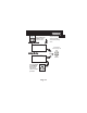
Installing the Humidity Module To install the Humidity Module the thermostat must be detached from the back plate. Plug the Humidity Module into the Humidity Module connector as shown in Figure 2 below. Follow the detailed instructions included with the Humidity Module accessory. Once the Humidity Module has been installed, you must adjust the Humidity jumper setting to HUM as shown in Figure 1 below. This will allow you to access the humidification and dehumidification setup steps.
Setting a Thermostat Jumper for Humidity Operation To control a MISC output for humidification, place the MISC1, MISC2, or MISC3 jumper on the terminal labeled HUM (see diagram below). This will supply 24VAC to the selected MISC terminal based on the humidification programming in the following pages. Only one of the three outputs (MISC1, MISC2, or MISC3) is required to have this jumper. For more information regarding the MISC1, MISC2, and MISC3 outputs, please see section 21.
Adjusting the Humidification Setpoint If your HVAC unit is equipped with a humidification system and the Humidity Module has been installed, the thermostat will provide power to the appropriate terminal on the backplate of the thermostat when the humidity in the building falls below the setpoint you have chosen. The value for this setpoint ranges from 0% to 60%. NOTE: Due to variations in environmental conditions, it is not always possible to achieve the desired humidification or dehumidification setpoint.
SECTION 10 Dehumidification Section 10 Contents: Configuring a Thermostat Output Jumper for Dehumidification Operation................................10.2 Adjusting the Dehumidification 10 Setpoint...................................10.3 Using Your Air Conditioner to Dehumidify.........................10.4 Using the Reheat Function..................................10.5 Using the DEHUM Terminal..................................10.
Setting a Thermostat Jumper for Dehumidification Operation To control a MISC output for dehumidification, install the Humidity Module and place the Humidity Jumper on HUM (see page 9.2). Then place the MISC1, MISC2, or MISC3 jumper on the terminal labeled DEHUM (see diagram below). This will supply 24VAC to the selected MISC terminal based on the programming in the following pages. Only one of the three outputs (MISC1, MISC2, or MISC3) is required to have a jumper.
Adjusting the Dehumidification Setpoint Dehum Terminal: If a MISC terminal is selected for DEHUM operation (see page 10.2), then the thermostat will provide power to this terminal when the humidity in the building is above the setpoint you have chosen. See page 10.6 for detailed programming instructions. To utilize this feature your HVAC unit must be equipped with a DEHUM terminal.
Using Your Air Conditioner to Dehumidify If Cool to Dehumidify is on and the Humidity Module is installed, the thermostat has the ability to initiate a cooling cycle for advanced dehumidification operation. When the thermostat detects the humidity percentage is above the setpoint for dehumidification, and heating or cooling is not on, the thermostat will force the compressor to run with the fan, thus reducing moisture in the air.
Using the Reheat Function This feature allows the thermostat to turn on Electric Heating (W2) during Cool to Dehumidify to maintain room temperature until the dehumidification setpoint is reached. The cooling cycle will allow for the dehumidification of the air to occur while the Electric Heating will allow for a constant room temperature. If Reheat is enabled the Aux icon will appear on the display during Cool to Dehumidify operation. MODE PROGRAM MODE Press the MODE button.
Using the Dehum Terminal If you configure a MISC output jumper for DEHUM, it may be programmed to operate in one of two ways: 1) Normally Closed (NC): The thermostat will de-energize the DEHUM terminal to allow the fan to run in low speed when there is a call for 1st stage cooling and the room humidity is greater than the dehumidification setpoint.
SECTION 11 Viewing Equipment Run-Times Section 11 Contents: Viewing the Heat Run-Time.................................11.2 Viewing the Cool Run-Time.................................11.3 11 Viewing the Override Run-Time.................................11.4 Viewing the Humidifier Run-Time................................ 11.5 Viewing the UV Light Run-Time.................................11.6 Page 11.
Viewing the Heat Run-Time - Energy Watch This display will track the number of hours that your heating system has been operating. Press the FAN button to reset the counter. MODE PROGRAM MODE Press 11 FAN Press the MODE button. While holding the MODE, press the PROGRAM button to enter Setup screens. Press the MODE button repeatedly until this setup screen appears. 0 Counts the number of hours Heat has been running. Press FAN to reset the Energy Watch* Heat counter. (0 - 1999 hrs.
Viewing the Cool Run-Time - Energy Watch This display will track the number of hours that your cooling system has been operating. Press the FAN button to reset the counter. MODE PROGRAM MODE Press FAN Press the MODE button. While holding the MODE, press the PROGRAM button to enter Setup screens. Note: Press the MODE button momentarily to move through the setup screens. Press and hold the MODE button to move backwards through the setup screens.
Viewing the Override Operation Run-Time This display will track the number of hours that your thermostat has been operating in the Override mode (see page 6.5 & 18.1). Press the FAN button to reset the counter. MODE PROGRAM MODE Press 11 FAN Press the MODE button. While holding the MODE, press the PROGRAM button to enter Setup screens. Press the MODE button repeatedly until this setup screen appears. 0 Counts the number of hours Override has been active. Press FAN to reset the Override RunTime counter.
Viewing the Humidification Run-Time After your humidification system has been operating for the number of days set in step #17 below, the Service Humidify icon will appear. This counter keeps track of the number of days since the Service Humidify icon was reset. MODE PROGRAM MODE Press the MODE button. While holding the MODE, press the PROGRAM button to enter Setup screens. Note: Press the MODE button momentarily to move through the setup screens.
Viewing the UV Light Run-Time After the UV light has been operating for the number of days set in step #18 below, the Service UV Light icon will appear. This counter keeps track of the number of days since the UV light icon was last reset. MODE PROGRAM MODE Press the MODE button. While holding the MODE, press the PROGRAM button to enter Setup screens. Note: Press the MODE button momentarily to move through the setup screens. Press and hold the MODE button to move backwards through the setup screens.
SECTION 12 Electric Heat and Heat Pump Operation Section 12 Contents: Viewing the Heat Pump and Reversing Valve Jumper Setting.....................................12.2 Viewing the Electric Heat Jumper Setting.......................12.3 Using Emergency Heat............12.4 12 Page 12.
Viewing the Heat Pump and Reversing Valve Jumper Settings Steps 19 and 20 are ‘Read Only’ and may only be set with the jumpers on the circuit board of the thermostat. MODE PROGRAM MODE Press the MODE button. While holding the MODE, press the PROGRAM button to enter Setup screens. Press the MODE button repeatedly until this setup screen appears. Setup 12 ON = Heat Pump operation OFF = Gas Electric operation Note: Press the MODE button momentarily to move through the setup screens.
Viewing the Electric Heat Jumper Setting Placing the jumper on ELEC will cause the thermostat to turn on the fan immediately any time there is a heat demand. Since most gas furnaces control the fan, this feature should be off unless it is necessary for the thermostat to energize the fan with first stage heat. Step 21 is ‘Read Only’ and may only be set with the jumpers on the circuit board of the thermostat. MODE PROGRAM MODE Press the MODE button.
Using Emergency Heat ENTER EMERGENCY HEAT: Only available if you have a Heat Pump installed. To initiate the Emergency Heat feature, press the FAN button. While holding the FAN button press the UP button. The Cool setpoint display will read ‘EH’ (emergency heat). I2:00 Su Press for Emergency Heat FAN 73 Pm 74 HEAT OPERATION: During Emergency Heat operation the thermostat will turn on the fan and the 2nd stage of heat 12 when there is a demand for heat.
SECTION 13 Timers and Deadbands Section 13 Contents: Adjusting the Heat/Cool Differential..............................13.2 Adjusting the Cycles Per Hour..................................13.3 Adjusting the Deadband..........13.4 Adjusting the Minutes of 13 Run-Time Before the Next Stage...............................13.6 Selecting 2nd Stage Turn Off Temperature.....................13.7 Page 13.
Adjusting the Heat/Cool Differential The Heat and Cool setpoints will not be allowed to come any closer to each other than the value in this step. This minimum difference is enforced during Auto-Changeover operation. MODE PROGRAM MODE Press the MODE button. While holding the MODE, press the PROGRAM button to enter Setup screens. Note: Press the MODE button momentarily to move through the setup screens. Press and hold the MODE button to move backwards through the setup screens.
Adjusting the Cycles Per Hour The Cycles Per Hour setting limits the number of times per hour your HVAC unit may energize. For example, at a setting of 6 cycles per hour the HVAC unit will only be allowed to energize once every 10 minutes. The Cycles Per Hour limit may be overridden and reset by pressing the UP or DOWN buttons on the thermostat. MODE PROGRAM MODE Press the MODE button. While holding the MODE, press the PROGRAM button to enter Setup screens.
Adjusting the Deadband MULTI-STAGE OPERATION - Controls up to three Heat and two Cool stages. The 2nd Stage of heat or cool is turned on when: (A) The 1st Stage has been on for the time required (step #27, page 13.6). It is adjustable from 0-60 minutes and the default is two minutes. And (B) The temperature spread from the setpoint is equal to or greater than: the setpoint plus the 1st stage deadband (step #24, next page), plus the 2nd stage deadband (step #25, next page).
Adjusting the Deadband For more detailed information, please see the explanation on the previous page. MODE PROGRAM MODE Press the MODE button. While holding the MODE, press the PROGRAM button to enter Setup screens. Note: Press the MODE button momentarily to move through the setup screens. Press and hold the MODE button to move backwards through the setup screens. Press the MODE button repeatedly until this setup screen appears. (1 - 6 ) 24 2 25 2 26 2 Setup Adjust the deadband for the 1st stage.
Adjusting the Minutes of Run-Time Before the Next Stage For more detailed information, please see the explanation on page 13.4. MODE PROGRAM MODE Press the MODE button. While holding the MODE, press the PROGRAM button to enter Setup screens. Press the MODE button repeatedly until this setup screen appears. 0:02 Adjust the amount of time stage 1 must be on before stage 2 turns on. (0 - 60 min.) 13 0:02 Adjust the amount of time stage 2 must be on before stage 3 turns on. (0 - 60 min.
Selecting 2nd Stage Turn Off Temperature If ON is selected, the second stage of cooling or heating will remain energized until the thermostat reaches the setpoint on the thermostat display. If OFF is selected, the second stage of cooling or heating will turn off after reaching the 1st stage deadband (see page 13.4 for more information). Press the MODE button. While holding the MODE, press the PROGRAM button to enter Setup screens.
SECTION 14 Using the Programmable Output Section 14 Contents: 14 Configuring a Thermostat Output Jumper for Programmable Output Operation...................14.2 Time-Based Control of the Programmable Output...........14.3 Temperature-Based Control of the Programmable Output.....14.6 Internet/Phone Control of the Programmable Output...........14.7 Page 14.
Setting a Thermostat Jumper for Programmable Output Operation To control one of the MISC outputs using time, temperature, or Internet/phone based operation, place the MISC1, or MISC2, or MISC3 jumper on the terminal labeled PROG (see diagram below). This extra output will supply 24VAC to the selected MISC terminal based on the programming described in the following pages. Only one of the three outputs (MISC1, MISC2, or MISC3) is required to have this jumper.
Time-Based Control of the Programmable Output To operate one of the MISC outputs using time-based operation, set Advanced Setup step #30 (below) for Time i8:88. This extra output will supply 24VAC to the selected MISC terminal, which is especially useful for devices that require a start and stop time. Refer to page 14.4 - 14.5 for more details on programming this output. Possible TIME scenarios: 1) An exterior lighting system that needs to be energized every day between the hours of 8pm and 1am.
Time-Based Control of the Programmable Output Setup NC Programmable Output Polarity: NC = Normally Closed to turn off between the start and stop times in steps 34 and 35. NO = Normally Open to operate between the start and stop times NO in steps 34 and 35. Press MODE 7 Setup 7-Day Select 7-Day or 1-Day Programming: 7-Day = Different program for each day. 1-Day = Same program 1-Day every day.
Time-Based Control of the Programmable Output 9:00 Mo Pm Stop 35 Setup Adjust the programmable output stop time for Monday If Step 32 is set for 1-Day, then Day of the Week and Copy functions do not appear or apply. Press MODE Yes Select Yes to copy the previous day’s program to this day. Tu If No is selected: No If Yes is selected: 14 Press FAN Selecting Yes, then pressing FAN will copy the previous day’s program. If yes is selected each time, this routine will repeat.
Temperature-Based Control of the Programmable Output To operate a MISC output using temperature-based operation, program advanced setup step #30 (below) for temperature 88 . This extra output will supply 24VAC to the selected MISC terminal based on the temperature of RS1 and the setpoint in step #36 (below). Possible TEMPERATURE scenario: 1) An exhaust fan in the attic of a store that needs to be energized when the attic temperature is above 85 degrees. MODE PROGRAM MODE OFF Press the MODE button.
Internet/Phone Control of the Programmable Output To operate a MISC output using Internet/phone-based operation, program advanced setup step #30 for Aux (below). This terminal is especially useful for devices that can be energized via the Internet. Telephone control may also be available when the thermostat is connected to the Internet. Possible REMOTE scenarios: 1) Arm the alarm system in your building after you have left for the day. 2) Turn off your sign lights after arriving home.
SECTION 15 Programming Remote Sensor Operation Section 15 Contents: Installing the Remote Sensors...................................15.2 Controlling or Reading the Remote Temperature (RS1)...15.3 Averaging the Remote Sensor (RS1) with the Thermostat Sensor.....................................15.4 15 Page 15.
Installing the Remote Sensors The Remote Sensor measures indoor air temperature and sends this information to the thermostat; it measures temperature with a range of 32 to 99 F. The Remote Sensor is equipped with an OVERRIDE button which will place the thermostat into the override mode for up to four hours (see page 6.5 & 18.1). The Remote Sensor should be connected to the thermostat using solid conductor CAT 5, CAT 5e, or CAT 6 type network communication cable.
Controlling or Reading the Remote Temperature (RS1) The thermostat may be programmed to only READ the remote sensor, or to CONTROL to the remote sensor. Refer to advanced setup step #37, below. Read Only Sensor (RS1): If step #37 is set to only READ to the remote sensor, the thermostat will not use this sensor for temperature control. This sensor may be viewed by entering advanced setup (see below) and pressing and holding the MODE button to scroll backwards one step to setup step #48 (see page 22.4).
Averaging the Remote Sensor (RS1) with the Thermostat Sensor If step #37 is set to control to the remote sensor, the thermostat will ignore the reading of its internal temperature sensor and only display the temperature reading from the remote sensor. The degree icon on the thermostat will blink once per second to indicate that a remote sensor reading is being displayed. If step #38 is set to ON (see below), the thermostat will average its internal sensor with the wired temperature sensor connected to RS1.
SECTION 16 Programming the Dry Contact Section 16 Contents: Dry Contact Operation............ 16.2 Dry Contact Polarity.................16.2 Dry Contact Programming.......16.3 Random Start Operation..........16.4 16 Page 16.
Dry Contact Operation If the dry contact is going to be used, select YES in step #39. If the dry contact is not going to be used, select NO in step #39 below. DRY CONTACT POLARITY - The terminals may be set to be Normally Open (NO) or Normally Closed (NC) in step #40. If NO is selected the dry contact will operate when it is forced closed. If NC is selected, the dry contact will operate until it is forced open. MODE PROGRAM MODE Press the MODE button.
Dry Contact Programming OCCUPIED OR SERVICE THE CONDENSATE DRAIN PAN - If Occupied is selected in step #41 (below), when the dry contact is energized the thermostat will be forced into Occupied setpoints and the Occupied icon will blink (Section 6). The thermostat must be in Program On mode for this feature to have any effect. If Service Pan is selected, when the dry contact is energized the thermostat will lockout Y1 (compressor) and write Service Pan on the display. Press the MODE button.
Random Start Operation This feature allows a 2 to 30 second delay before energizing the thermostat outputs after any of these events: Loss of Power to the thermostat: When power to the thermostat is interrupted and then restored, Random Start will lockout the outputs of the thermostat for a random amount of time. This delay helps to keep multiple thermostats from energizing their outputs at the same time after a power outage.
SECTION 17 Light Activated Operation Section 17 Contents: Setting up the Thermostat for Light Activated Operation................................17.2 Adjusting the Light Sensor.....17.3 17 Page 17.
Setting up the Thermostat for Light Activated Operation A light sensor is provided on the thermostat for light activation. If the thermostat is set up to be light activated, the thermostat will enter Occupied and blink the Occupied icon when a light source is detected. When the thermostat is set up to be light activated, the time period programming for each day should be set to OFF (Section 6). The thermostat must be in Program On mode for light activation to have any effect. Page 17.
Adjusting the Light Sensor The light sensor can be adjusted for variable degrees of sensitivity. The sensitivity adjustment screw is located on the side of the thermostat, as illustrated below. Turning the screw clockwise increases the sensitivity of the sensor to light. To check for correct sensitivity, place the thermostat in the Program On mode. When the lights are on the thermostat should enter Occupied and the Occupied icon will blink on the display.
SECTION 18 Override Timer Operation How to Use the Override Timer During programmed, unoccupied periods, pressing the OVERRIDE button will temporarily force the thermostat into Occupied comfort settings for the number of hours programmed in step #43, below. For example, if the thermostat is programmed to be occupied from 8:00 AM to 5:00 PM, but a cleaning crew is scheduled to come into the building from 7:00 PM to 9:00 PM, then this setup step can be programmed for two hours.
SECTION 19 Programming Run-Time Alerts Section 19 Contents: Setting and Resetting the Service Filter (Fan Run-Time) Alerts........................................19.2 Setting and Resetting the UV Light Run-Time Alerts.............19.3 Setting and Resetting the Humidify Run-Time Alerts......19.4 19 Page 19.
How to Set and Reset the Service Filter (Fan Run-Time) Alert This counter keeps track of the number of hours of fan run-time whether the fan is energized in the Heating or Cooling modes, or in stand alone fan operation. The Service Filter icon will appear after the preset number of hours of fan run-time in step #45 (below) has been achieved. Setting this counter to zero in step #45 will prevent the Service Filter icon from ever appearing. MODE PROGRAM MODE Press the MODE button.
How to Set and Reset the UV Light Run-Time Alert This counter keeps track of the number of days since the UV Light counter has been reset. The UV Light icon will appear after the number of days has been achieved, as shown in step #46 (below). Setting the counter to zero in Step #46 will prevent the Service UV Light icon from ever appearing. MODE PROGRAM MODE Press the MODE button. While holding the MODE, press the PROGRAM button to enter Setup screens.
How to Set and Reset the Humidifier Run-Time Alert This counter keeps track of the number of days since the Service Humidify icon was last reset; this icon will appear after the number of days set in step #47 (below) has elapsed. Setting this counter to zero in step #47 will prevent the Service Humidify icon from ever appearing. MODE PROGRAM MODE Press the MODE button. While holding the MODE, press the PROGRAM button to enter Setup screens.
SECTION 20 Programming Holiday Mode When the thermostat is programmed for a Holiday mode, it will take effect at 12:00 am of the next day. In order for the Holiday mode to take effect the thermostat must be in the Program On mode. The thermostat will control to the Unoccupied cooling and heating setpoints set in Section 6, pages 6.2 and 6.3. Holiday setpoints will be enforced for the number of days specified in step #1 (0 - 99 days).
Programming Holiday Mode (continued) HOLIDAY DISPLAY - When the thermostat is placed into the Holiday mode, the thermostat will display the screen shown below. 2 y To return the thermostat to normal operation from Holiday mode, press the HOLIDAY button and adjust the number of days in step #1 to zero (see previous page). Press the HOLIDAY button to return to normal operation.
SECTION 21 Configuring the MISC Outputs Section 21 Contents: Configuring the Jumpers........21.2 Explanation of Jumper Settings..................................21.3 21 Page 21.
Configuring the Jumpers For additional flexibility, your thermostat has three configurable outputs. These outputs are designed to have different functions depending on how the jumpers are set (below). Each output, labeled MISC1, MISC2, and MISC3 may be set for one of the five choices available.
Explanation of Jumper Settings W3 JUMPER SETTING If the jumper for MISC1, MISC2, or MISC3 is set to W3, the corresponding MISC screw terminal on the backplate will control a third stage of heat. W3 MULTI-STAGE OPERATION EXPLAINED - PAGE 13.4 The 3rd Stage of Heat is turned on when: (A) The 1st and 2nd stages have been on for the time required (steps 27 and 28, page 13.6). It is adjustable from 0-60 minutes and the default And is two minutes.
Explanation of Jumper Settings (continued) HUM JUMPER SETTING If the jumper for MISC1, MISC2, or MISC3 is set to HUM, the corresponding MISC screw terminal on the backplate will control a humidification system.
Explanation of Jumper Settings (continued) ECON JUMPER SETTING If the jumper for MISC2 or MISC3 is set to ECON, the corresponding MISC screw terminal on the backplate will be connected to an economizer. ECONOMIZER OPERATION - If your HVAC unit is equipped with an economizer system, the thermostat will provide power to the MISC2 or MISC3 terminal of the thermostat when the thermostat is in an occupied time period.
SECTION 22 Factory Defaults, Calibration, and Sensors Section 22 Contents: Resetting the Thermostat to the Factory Default Settings........22.2 Calibrating the Temperature and Humidity Sensors...........22.3 Viewing the Remote Temperature Sensors............22.4 22 Page 22.
Resetting the Thermostat to the Factory Default Settings (for default values see page 24.1) If, for any reason, you desire to return all the stored settings back to the factory default settings, follow the instructions below. WARNING: This will reset all Time Period and Advanced Programming to the default settings. Any information entered prior to this reset may be permanently lost. I2:00 Su MODE MODE FAN Place the thermostat in the OFF mode. Press and hold the MODE button.
Calibrating the Temperature and Humidity Sensors Under normal circumstances it will not be necessary to adjust the calibration of the temperature and humidity sensors. If calibration is required, please contact a trained HVAC technician to correctly perform the following procedure. I2:00 Su MODE MODE FAN Place the thermostat in the OFF mode. Press and hold the MODE button. While holding the MODE button, press and hold the FAN button for 5 seconds. All icons will appear on the display.
Viewing the Remote Temperature Sensors Each sensor is programmed with a “hard-coded” address that the thermostat “scans” in order from lowest to highest. Therefore, in order to determine which sensor corresponds to the number on the setup screen you will need to disconnect each sensor from the group in order to determine which sensor number reads dashes. Press the MODE button. While holding the MODE, press the PROGRAM button to enter Setup screens. MODE PROGRAM MODE Remote Sensor #1.
SECTION 23 Accessories ACCESSORY PORT - The RJ11 Jack is used to connect the T2900SCH to the IR Receiver (ACC0431) for wireless communication or the EZ Programmer (ACC0432) for easy downloading or uploading of thermostat information. The Accessory Port is located on the bottom of the thermostat. RJ11 Type Jack IR RECEIVER / REMOTE CONTROL (optional accessory) - When the IR Receiver is connected, the thermostat can be controlled using an IR Remote Control.
SECTION 24 Advanced Setup Table Step# Description 1 Programmable Thermostat 2 Auto-Changeover Thermostat 3 Fan Off Delay 4 Fan Purge 5 Thermoglow Backlight 6 F or C 7 Security Level 8 Max Heat Setpoint 9 Min Cool Setpoint 10 Cool to Dehumidify 11 Maximum Dehum Overshoot 12 Reheat Operation 13 DEHUM Terminal Polarity 14 Energy Watch Heat Timer 15 Energy Watch Cool Timer 16 Override Run-Time 17 Reset Service Humidify Icon 18 Reset UV Light Icon 19 Heatpump Jumper Setting 20 Reversing Valve Jumper Setting 2
SECTION 25 A Accessory Port, 23.1 Alerts see Run-Time Auto adjust temperature, 1.4, 4.8 changeover, 2.3, 4.5, 4.7, 24.1 differential, see Differential fan, 7.2 icon, 2.3 lockout, 4.3 mode, 1.3 AuxHeat icon, 2.5 Average remote sensors, 15.4 thermostat sensor, 15.4 automatically, 15.4 B b reversing valve, 12.2 Buttons down, 1.2, 2.2, 8.3, 12.4 fan, 1.4, 2.2, 7.2, 12.4, 22.2 Index front panel, 2.2 humidity, 2.2, 5.3, 9.4, 10.4 Holiday, 2.2, 5.2, 15.3, 20.1 mode, 1.3, 2.2, 4.2, 8.3, 22.2 outdoor, 2.2, 5.
SECTION 25 display, 2.4 setting, 1.2, 3.2 Deadband 1st stage, 13.4-13.5, 24.1 2nd stage, 13.4-13.5, 21.3, 21.5, 24.1 3rd stage, 13.4-13.5, 21.3, 24.1 Dehumidify cool to, 10.4, 24.1 Aux icon, 2.5, 10.5 DEHUM jumper, 10.6 icon, 2.5 setpoint, 10.3 Delay fan-off, see Fan time between stages, see Time Delay Differential heat and cool, 13.2, 24.1 humidify and dehumidify, 9.2, 10.2 Disabled Keypad see Keypad Lockout Drain Pan Overflow Alarm, see Dry Contact Dry Contact occupied, 16.3, 24.1 operation, 16.2, 24.
SECTION 25 12.4 minutes of runtime, 13.4, 13.6, 24.1 2nd stage deadband, see Deadband emergency heat, 12.4 minutes of runtime, 13.4, 13.6, 24.1 3rd stage deadband, see Deadband W3, 21.3 AuxHeat icon, 2.5 deadband, see Deadband droop, see Deadband electric/heat pump, 12.2-12.3 icon, 2.3 indicator, 2.2 mode, 1.3 program, see Program run-time, see RunTime setpoint, 1.3-1.4, 6.2-6.3 Heat Pump AuxHeat, 2.5 emergency heat, 12.4 jumper setting, 12.2 Index Hi icon, 2.5, 5.2 security setpoint, 8.4 temperature, 5.
SECTION 25 random start, 16.4 sensor, 17.2 adjustment, 17.3 Locked Indication see Keypad Lockout Lo icon, 2.5, 5.2 security setpoint, 8.4 temperature, 5.2 M Manual changeover, 4.4, 4.6 cool, 4.3 heat, 4.3 Maximum Outdoor Temperature, see Hi Minimum Outdoor Temperature, see Lo MISC jumper, see Jumpers output, 21.2-21.5 Mode, 1.3, 2.3 Multi-stage Operation, 13.4 N Non-Programmable Index Thermostat, 4.2, 4.4-4.5 Normally Open/Closed, dry contact, 16.2 programmable output, 14.4, 14.6-14.
SECTION 25 override, see Override setpoint limits, 8.4 tips, 6.4 worksheet, back page Programmable Output Internet/phone control, 14.7 jumper setting, 14.2, 21.3 temperature-based control, 14.6 time-based control, 14.3 Programmable Thermostat, 4.2 R Random Start, 16.4 Red Indicator, 2.2 Reheat during cool to dehumidify, 10.5 electric heating, 10.5 function, 10.5 W2, 10.5 Remote Sensor averaging, 15.4 calibrate, 22.3 Control to, 15.315.4, 22.1 degree icon blink, 15.2-15.4 Index icon, 2.
SECTION 25 security, 8.4 unoccupied, 6.2-6.3 Setup Icon, 2.4 Simplest Operation, 4.2-4.3 Smart Fan, 7.2 T Terminal, MISC, see MISC Thermostat Sensor averaging, 15.4, 24.1 calibrate, 22.3 Time, see Clock Time Delay, compressor lockout, 13.3 cycles per hour, 13.3, 24.1 1st to 2nd stage, 13.6, 24.1 2nd to 3rd stage, 13.6, 24.1 Time Schedule, see Program Index operation, 6.4 override, see Override setpoint, 6.2-6.3 UV Light icon, 2.
Section 26 Warranty One-Year Warranty - This Product is warranted to be free from defects in material and workmanship.