
installation instructions


Page 4L124 0516A
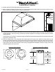
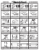
Centerline
Of Hood
Electrical
6" Outlet
Wall Side
Vent
Hole
1 7⁄8”
1 ¾”
5 ¼”
Blower
Exhaust
Outlet
2"
12"
6" Round
Electrical
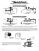
1 ¾”
Centerline
of Hood
8” Outlet
Vent
Holes
5 ¼”5 ½”
Wall Side
2"
12"
Blower
Exhaust
Outlet
8" Round
Installation Details Continued
5) Remove the hood and the painted round duct from their packaging and place the back of the hood on the oor or
countertop in front of the wall where it will hang. The painted round duct will be used later in Step 12.
6) Remove the shipping tape that is securing the E-Z Clean shield(s) inside the hood. Remove the E-Z Clean shield(s) by
lightly pulling it toward the front of the hood. Gently close the back draft damper(s) from the top side of the hood. To
remove the blower housing(s), unsnap the suitcase latches (one on each side of the housing). The housing(s) should
be pulled forward and gently “tipped” to clear the blower wheel(s) and then out of the hood.
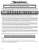
7) Remove the three screws retaining the blower motor(s). Unplug
and remove the motor(s), taking care not to damage the blower
wheel(s). It is not necessary to remove the blower wheel(s)
from the motor(s).
Connection Diagram (30” - 48”Widths)
Connection Diagram (36” - 48” Widths)
300 CFM B100 Single Blower
(Top View)
(Front View)
600 CFM B200 Dual Blower
(Top View)
(Front View)