
installation instructions


Page 5L124 0516A
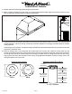
9) Mark the wall with a level, horizontal line that is located 43” above the cooking surface. Measure where the center (left
to right) of the hood will be and mark the horizontal line on the wall with a short, vertical centerline.
10) Remove the screws inside the top of the back of the hood that retain the wood mounting strip that is recessed in the
mounting channel. Note: Some retaining screws may be located inside the motor box. Remove the wood mounting strip
from the back of the hood and place the top edge of the strip on the level horizontal line on the wall. Referencing the
vertical centerline from Step 9, place the mounting strip so it is centered (left to right) on the wall in the space where
the hood will be located. In line with at least two wall studs, drill pilot holes in the wood mounting strip to prevent
splitting. Using proper hardware, attach the mounting strip to the wall and into the wall studs.
11) Hang the hood by aligning the channel at the top of the back of the hood over the wood mounting strip on the wall.
While holding the hood in place, mark locations on the wood mounting strip through the two mounting holes in the
channel at the top of the hood. Some mounting holes may be located inside the motor box. Remove the hood and drill
3/32” pilot holes at the center of the marks in the wood mounting strip to prevent splitting.
12) Remove the wire channel cover from the back of the painted round duct. Insert the painted round duct, crimped end up,
into the exhaust collar on the hood. Seal joint with duct tape. Insert the electrical wire from the service panel through
the electrical wire clamp on the motor box. Tighten the wire clamp. Guide the electrical wire into the electrical wire
channel and press the wire channel cover back into place, taking care not to pinch the electrical wire.
13) Lift the hood into position while aligning the painted round duct with the ceiling collar. As the hood is lifted into position,
secure the slack in the electrical wire to ensure that the electrical wire does not get pinched. Secure the hood to the
wood mounting strip by installing the screws (previously removed from the strip in Step 10) into the pilot holes drilled
in Step 11.
14) From inside the hood, using UL listed wire nuts, attach the “neutral” wire to the white lead inside the motor box, the
“hot” wire to the black lead inside the motor box, and the ground wire to the green lead inside the motor box.
Installation Details Continued
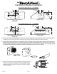
8) Install an appropriate 1/2” UL listed electrical wire clamp through the motor box electrical opening on top of the hood.
Install electrical wiring from the service panel to the hood location for the motor box. Consult the connection diagram
(on previous page) for further details on electrical placement. Extend wire to the hood. Electrical hook up will occur
before the hood is installed on the wall.
Warning: Do not operate hood without proper ground connection.
15) Plug the motor(s) into the hood and reinstall the blower motor retaining screws that were previously removed in
Step 7.
16) Replace the blower housing and the blower shield. Make sure that the damper(s) open and close smoothly.
17) Refer to the Owner Maintenance Guide Operating Instructions for proper hood operation. Test all blower and light
functions to ensure they are operating properly.
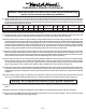
Model Volts Amps Hz RPM
CFM
SP@0.0"
Equivalent CFM
•
CFM
SP@0.1"
CFM
SP@0.2"
CFM
SP@0.3"
Minimum Round
Duct Size
Sones
#
B100 Single 115 2.5 60 1550 300 450 273 245 225 6" (28 in.
2
) 5.4
B200 Dual 115 4.0 60 1550 600 900 531 480 430 8" (50 in.
2
) 6.5
• BecausetheMagicLung
®
blowerusescentrifugalltrationratherthanconventionalbafeormeshlters,theMagicLung
®
blowercanhandlecookingequipmentwithhighercubicfeetperminute(CFM)requirementsandcandeliverequivalentCFMmuchmore
efcientlythanotherltrationsystems.WhencomparingtheMagicLung
®
withotherblowerunitsmadebyothermanufacturers,usethe“EquivalentCFM”.
#
RatingsinaccordancewiththeStandardTestCodebytheEnergySystemsLaboratoryoftheTexasEngineeringExperimentStation.
Warning: Make sure power is o and locked at the service disconnecting
means on the service panel during installation.