
Installation Instructions


Page 5L119 0611A
Installation Details Continued
8) Install an appropriate 1/2” UL listed electrical wire clamp through each motor box electrical opening on top of the
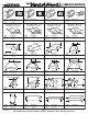
hood. Install electrical wiring from the service panel to the hood location for each motor box. Consult the connection
diagrams (on previous page) for further details on electrical placement.
Method 1: Extend wire to the hood. Electrical connection(s) will occur before the hood is installed on the wall.
Method 2: Extend wire to 24” above the countertop. Electrical connection(s) will occur after the hood is installed on
the wall.
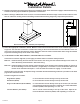
9) Remove the duct cover from its packaging. Place the duct cover over the top of the hood taking care to align the single
ange on top of the hood between the double ange on the bottom of the duct cover. Press the duct cover down to
engage the anges. Lift the hood and hold in place on the wall in the location where it will be installed. Lightly mark
the wall with a short horizontal mark along the bottom edge of the hood.
10) Remove the hood and duct cover assembly from the wall. On the back side of the hood, measure the distance between
the bottom edge of the hood and the top edge of the wood mounting strip. Measure this distance above the horizontal
line made in Step 9 and lightly mark the wall with a level, horizontal line. Measure where the center (left to right) of the
hood will be and mark the upper horizontal line on the wall with a short vertical centerline.
11) Remove the screws inside the top of the back of the hood that retain the wood strip that is recessed in the mounting
channel. Note: Some retaining screws may be located behind the blower(s). Remove the wood mounting strip from
the back of the hood and place the top edge of the strip on the upper, level horizontal line on the wall. Referencing the
vertical centerline from Step 10, place the mounting strip so it is centered (left to right) on the wall in the space where
the hood will be located. Drill pilot holes in the strip to prevent splitting. Using proper hardware, attach the mounting
strip to at least two wall studs.
12) FOR BACK VENTING APPLICATIONS ONLY. IF NOT BACK VENTING, PROCEED DIRECTLY TO STEP 13.
Note: Wall studs may interfere with back venting installations. Additional framing may be required. It is necessary to
cut duct access hole(s) in the wall prior to installing the hood.
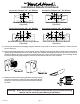
To accomplish this, rst remove and set aside the duct cover that was previously installed in Step 9. Hold the hood
on the mounting strip by aligning the channel at the top of the back of the hood over the wood mounting strip on the
wall. Place the appropriate elbow(s) on top of the hood in line with the hood exhaust collar(s). On the wall, trace around
the elbow(s). Remove the hood and elbow(s) from the wall. Cut around the outside of the traced line(s), avoiding wall
studs. Install the duct from the outside of the home to the opening in the wall. Use duct tape to seal joints. Note: If
using Method 1, place the duct cover back onto the top of the hood.
13) Hang the hood on the mounting strip by aligning the channel at the top of the back of the hood over the wood mounting
strip on the wall. While holding the hood in place, mark locations on the mounting strip through the two mounting
holes in the channel at the top of the hood. Some mounting holes may be located behind the blower(s). Remove the
hood and drill 3/32” pilot holes at the center of the marks in the wood strip to prevent splitting.
14) FOR BACK VENTING APPLICATIONS ONLY. IF NOT BACK VENTING, PROCEED DIRECTLY TO STEP 15.
Place the appropriate elbow(s) on the top of the hood. Elbow(s) should be placed with the non-crimped end(s) on the
inside the collar(s) of the exhaust outlet(s). Use duct tape to seal joints.
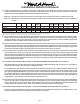
Model Volts Amps* Hz RPM
CFM
SP@0.0"
Equivalent CFM
•
CFM
SP@0.1"
CFM
SP@0.2"
CFM
SP@0.3"
Minimum Round
Duct Size
Sones
#
B100 Single 115 1.5 60 1550 300 450 273 245 225 6" (28 in.
2
) 5.4
B200 Dual 115 2.9 60 1550 600 900 531 480 430 8" (50 in.
2
) 6.5
B200 Dual & B100 Single 115 4.4 60 1550 900 1350 804 725 655 VP562: 10" (79 in.
2
) 6.3
Two B200 Duals 115 5.8 60 1550 1200 1800 1062 960 860 VP563: 12" (113 in.
2
) 6.6
* Add 0.5 amp for each halogen light.
• BecausetheMagicLung
®
blowerusescentrifugalltrationratherthanconventionalbafeormeshlters,theMagicLung
®
blowercanhandlecookingequipmentwithhighercubicfeetperminute(CFM)requirementsandcandeliverequivalentCFMmuchmore
efcientlythanotherthanotherltrationsystems.WhencomparingtheMagicLung
®
withotherblowerunitsmadebyothermanufacturers,usethe“EquivalentCFM”.
#
RatingsinaccordancewiththeStandardTestCodebytheEnergySystemsLaboratoryoftheTexasEngineeringExperimentStation.