
Installation Instructions

Page 3
L154 0514A
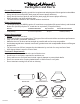
Electrical
10" Round
6" Round
Electrical
Installation Details
1) Read all instructions thoroughly before beginning installation. Note: These instructions apply to standard liners only.
Custom liners may require additional specication consideration.
2) When installing a MSLD wall mount liner (19 1/4” deep), it is recommended that the bottom edge of the liner be located
no more than 24” - 27” above the cooking surface for optimum performance. For MPSLD wall mount liners (22 1/2”
deep), it is recommended that the bottom edge of the liner be located no more than 27” - 30” above the cooking surface
for optimum performance.
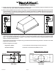
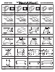
3) Install the duct from the outside of the home down to the location of the exhaust outlet on the top of the liner allowing
room for the transition (if applicable). If a transition is used, install duct down to the location of the transition outlet
plus 1”. This will allow the transition to engage 1” inside of duct. Consult the connection diagrams (below) for further
details on exhaust outlet placement.
Use duct tape to seal all joints. A complete listing of available Vent-A-Hood ducting materials is included on the back
page of this instruction sheet.
Transition heights are as follows:
Single Blower (M600): 6” round duct will connect directly to the top of the liner.
Dual Blower (M1200): Included 10” round transition (VP566) is 9” tall.
MSLD Liner MPSLD Liner
M1200 Connection Diagram
Dual Blower
(Top View)
Single Blower
(Top View)
M600 Connection Diagram