
Installation Instructions

Page 5
L154 0514A
Installation Details Continued
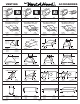
12) To conrm a ush alignment into the decorative enclosure, temporarily snap the lter/control section into the liner
shell. Adjust corner screws if necessary.
13) Unsnap the lter/control section from the bottom of the liner shell and insert wood screws (included) in the remaining
holes along the bottom edge of the liner shell.
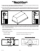
14) Raise the blower plate into the liner shell rst aligning the ducting (M600 blower only) and then aligning the blower
mounting studs to the holes in the blower plate. Secure the blower assembly with the nuts provided. This duct connection
typically cannot be sealed.
15) Hold the lter/control section just below the liner shell and connect the motor harness and power cord to the sockets
in the lter/control section electrical cover. Snap the lter/control section to the bottom of the liner shell. Secure the left
and right lter/control section safety straps to the studs on the inside ends of the liner shell with the nuts previously
removed in Step 5.
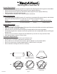
16) To install the bafe lter, hold the lter with the knob facing down and toward the front of the hood. Insert the back of
the lter into the back lter channel with enough force to compress the lter spring. Raise the front of the lter inline
with the front lter channel and slowly release the spring force.
To remove the bafe lter, push the lter knob toward the back lter channel to compress the lter spring. Lower the
front of the lter below the front lter channel and slowly release the spring force.
17) Refer to the Owner Maintenance Guide Operating Instructions for proper hood operation. Test all blower and light
functions to ensure they are operating properly.