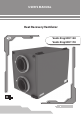
USER’S MANUAL Heat Recovery Ventilator Vents Brig HRV 120 Vents Brig HRV 170
Brig HRV 120 (170) CONTENT Introduction ............................................................................................... Application ................................................................................................. Delivery set ................................................................................................. Unit designation key ............................................................................... Basic dimensions .................................
INTRODUCTION This user’s manual combines technical description, operation and service manual, technical data sheet and installation guidelines for the heat recovery ventilator Brig HRV 120 (170), hereinafter referred to as the unit. APPLICATION The unit is designed to save thermal energy by means of heat recovery and is one of the energy saving components used in the buildings and premises. The ventilator is a component unit and is not designed for independent operation.
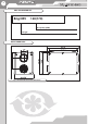
Brig HRV 120 (170) UNIT DESIGNATION KEY Brig HRV 120(170) Air capacity [CFM] Unit type HRV - Heat Recovery Ventilator BASIC DIMENSIONS Fig.
TECHNICAL DATA The unit is designed for indoor application with the ambient temperature ranging from +34 °F (1 °С) up to +122 °F (50 °С). Ingress Protection rating: IP44 for the unit motors. IP 22 for the assembled unit connected to air ducts. The unit net weight is 66 lbs (30 kg). The unit series designation, basic overall and connecting dimensions are shown in fig. 1. The unit design is regularly being improved, so some models can slightly differ from those ones described in this manual.
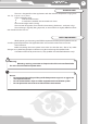
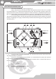
Brig HRV 120 (170) STRUCTURE AND OPERATING LOGIC The unit has the following operating logic (fig. 2): Warm stale extract air from the room flows through the air ducts to the unit, is purified in the extract filter and is supplied to the heat recovery core and exhausted outside by exhaust fan. Clean cold air from outside is moved by supply fans to the unit where it is purified through the supply filter. Then clean air flows through the heat recovery core and is supplied to the room by supply fan.
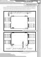
MOUNTING AND SETTING-UP min 4” While mounting the unit provide enough access for the unit maintenance and servicing. Mount the unit to ceiling with threaded rods fixed inside the dowels attached to the ceiling or by means of the belts that are rigidly fixed to horizontal plane (fig. 3). The unit can be installed on mounting supports with adjustable height for connection to the drain system (fig. 4). 20” Fig. 3. Ceiling unit mounting example Fig. 4.
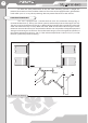
Brig HRV 120 (170) To attain the best performance of the unit while mounting provide a straight 20’’ (500 mm) duct section in front and behind the unit. The unit must be equipped with a grille with the mesh width up to 1/2” or any other protecting device to prevent free access to the unit fans. CONDENSATE DRAINAGE The unit is equipped with a condensate drain hose for condensate drainage (fig. 5). Connect the drain hose (1), U-trap (3) and drain system (5) with metal, plastic or rubber pipes (2 and 4).
Connection to power mains Cut power supply off before any operations with the unit. The unit shall be connected to power mains by a duly qualified electrician only. Rated values of the electrical parameters are shown on the rating plate. Any modifications of the internal connections are not allowed and will void the warranty. The unit is designed for connection to single-phase ac 120 V / 60 Hz power mains.
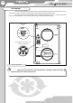
Brig HRV 120 (170) UNIT CONTROL The unit is controlled by a three-position speed switch that enables low-speed modes «Low» and «Med» as well as «Stand by» mode which enables total air quality control (fig. 7). Up to five external control devices may be connected to the terminals 2-11 that turn the unit to high-speed ventilation in case of activation of any of the control devices (fig. 7). Three-speed switch Terminals for connection of the remote control panel Fig. 7.
1. Remote control (Thermostat). Set the three-position switch into the Stand by position to activate the remote control. Remote control (thermostat) functions: Unit turning on/off Setting air flow Displaying indoor air temperature • • • 2. CO2 sensor. Recommended for use in office buildings and public premises. When carbon dioxide concentration exceeds the set point, the unit changes into the High Speed Mode. 3. Humidistat. The humidistat is used for indoor humidity control.
Brig HRV 120 (170) SERVICING AND MAINTENANCE Servicing of the unit is required 3-4 times per year. Besides general cleaning, the following operations are required: 1. Filter maintenance (3-4 times per year). Dirty filters increase air resistance in the system and reduce supply air flow to the premises. Clean or replace the filters as often as required, but at least 3-4 times per year. Clean the filter with running water or a vacuum cleaner. Contact your local supplier for new filters. 2.
TROUBLESHOOTING Possible malfunctions and fault handling Problem Possible reasons Power supply is off. The fan(s) do(es) not start running. Thermal fuse is melted. The extract filter is clogged. Cold supply air. The heat recovery core is frozen. Too low set rotation speed. The filters, fans or heat recovery core are clogged. Low air capacity. The ventilation system is clogged or damaged. The impeller(s) is (are) clogged. Noise, vibration. Water leakage Fan screw tightening is loose.
Brig HRV 120 (170) STORAGE AND TRANSPORTATION RULES Store the unit in the manufacturer’s original packing box in a ventilation premise with the temperature range from +14 °F (-10 °С) up to +104 °F (+40 °С) and relative humidity less than 60% (at +68 °F (+20 °С)). Vapors or particles which can cause corrosion or damage the insulation or connection tightness are not allowed in the stock. Use hoist equipment for loading and storage operations to prevent the unit falling or excessive oscillation.
BRIG_HRV 120(170)_02(USA_120)_EN