
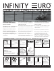
Instructions / Assembly

2
03-infinityEuro rev. 2017-05-17
©2013-2017 Jewett-Cameron Company • www.jewettcameron.com • Customer Service: 800-955-2879
Customer Service: 1-800-955-2879 Fax: 503-647-2272
HELPFUL TIPS • CONSEILS PRATIQUES • SUGERENCIAS ÚTILES
Planning and Layout ................................... 3
Parts Identification ............................... 4 - 5
How to Build A Panel .................................. 6
Surface-Mount Installation ................. 7 - 8
In-Ground Installation ....................... 9 - 10
Gate Assembly & Installation ........... 11 - 12
Hanging Gate ................................................ 13
Sloped Terrain Installations .................... 14
FAQ ................................................................. 15
Warranty ...................................................... 20
TABLE OF CONTENTS • TABLE DES MATIÈRES • TABLA DE CONTENIDOS
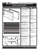
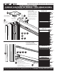
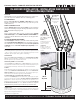
• Posts must be aligned at 72 INCHES
ON CENTER, refer to post installation
on PAGE 3 STEP 2D
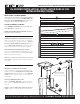
• We allow for a tight fit when stack-
ing the fence composite board onto
a fence aluminum board, you may
need to use the rubber mallet to tap
the composite board into place. Be
careful not to damage the tongue of
the board you are tapping on.
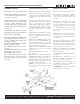
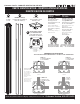
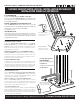
• The BRACKET (G1) of the TOP and
BOTTOM FRAME KIT (G) #EF40408
must slide down the BACK CHANNEL
(closest to the center of the post).
Refer to PAGE 6
• The UNIVERSAL POST (H) has 3
channels that allow for END, LINE,
CORNER or T-POST applications see
PAGE 5. Your posts are delivered
with 1 open channel and 2 with the
CHANNEL COVER (H1) installed. These
channel covers slide out for access
to the inside of the channel. Save
these covers! You can use them as
additional support for the bottom
board of the fence panel, and to cov-
er any open channels at the tops and
bottoms of the posts. Just cut to size
and slide down the FRONT CHANNEL
of the post, at the same level as the
BOTTOM BRACKET (G1). See diagram
on PAGE 8
• Les poteaux doivent être alignés à
1,82 M AU CENTRE, lisez l’installation
des poteaux à la PAGE 3, ÉTAPE 2D
• Nous permettons un ajustement
serré lors de l’insertion d’un pan-
neau de clôture en composite dans
un panneau de clôture en alumin-
ium, vous aurez peut-être besoin
d’un maillet en caoutchouc pour
mettre en place le panneau en com-
posite. Faites attention à ne pas en-
dommager la languette du panneau
lorsque vous tapez.
• L’ÉQUERRE (G1) de LA TROUSSE DE
STRUCTURE DU HAUT ET DU BAS (G)
#EF40408 doit glisser dans le CANAL
ARRIÈRE (le plus près du centre du
poteau). Voir la PAGE 6
• Le POTEAU UNIVERSEL (H) a 3 rails
qui permettent les applications pour
poteaux d’EXTRÉMITÉ, de LIGNE, de
COIN ou de POTEAU-T, voir PAGE 5.
Vos poteaux sont livrés avec 1 rail
ouvert et 2 COUVERTURES DE CANAL
(H1) installées. Ces trois couvertures
de rail se glissent pour accéder à
l’intérieur du rail. Conservez ces
couvertures! Vous pouvez les utilis-
er comme soutien supplémentaire
pour le panneau du bas du pan-
neau de clôture et pour couvrir tout
rail ouvert au-dessus ou à la base
des poteaux. Coupez simplement à
la bonne taille et glissez-là dans le
CANAL AVANT du poteau, au même
niveau que l’ÉQUERRE DU BAS (G1).
Voir le diagramme à la PAGE 8
• Los postes se deben alinear a 1,83 m
EN EL CENTRO, consulte la instalación
de postes en la PÁGINA 3 PASO 2D.
• Las tablas de la cerca deben que-
dar bien ajustadas a la estructura de
aluminio; para ello, deberá usar un
mazo de goma para fijar las tablas en
su lugar. Tenga cuidado de no dañar
la lengüeta de la tabla al martillar.
• El SOPORTE (G1) del KIT DE LA
ESTRUCTURA SUPERIOR e INFERIOR
(G) #EF40408 se debe desplazar por
el CANAL POSTERIOR (más cercano al
centro del poste). Consulte la PÁGINA 6
• El POSTE UNIVERSAL (H) tiene 3 ca-
nales para usar con POSTES DE TER-
MINAL, DE LÍNEA, DE ESQUINA o “T”,
consulte la PÁGINA 5. Los postes vi-
enen con 1 canal abierto y 2 canales
tapados con una CUBIERTA DE CANAL
(H1). Para acceder al canal, deslice la
cubierta de canal. ¡Guarde las cubi-
ertas! Puede usarlas como soporte
adicional para la tabla inferior del
panel de la cerca y para tapar los ca-
nales que queden abiertos en la par-
te superior e inferior de los postes.
Corte el tamaño necesario y deslice
por el CANAL FRONTAL del poste, al
mismo nivel del SOPORTE INFERIOR
(G1). Consulte el diagrama en la
PÁGINA 8
Planification et Disposition ...................... 3
Identification Des Pièces .................... 4 - 5
Comment Construire Un Panneau .......... 6
Installation en Surface ........................ 7 - 8
Installation Dans le Sol ..................... 9 - 10
Assemblage de la Porte et
Installation .......................................... 11 - 12
Accrochage De La Porte ........................... 13
Installation Sur Un Terrain En Pente .... 14
FAQ ................................................................. 15
Garantie ....................................................... 20
Planificación y Diseño ................................ 3
Identificación De Partes ....................... 4 - 5
Cómo Armar Un Panel ................................. 6
Instalación Sobre la Superficie ........... 7 - 8
Instalación Bajo Tierra ...................... 9 - 10
Ensable E Instalación de la Puerta ... 11 - 12
Colocación de la Puerta ........................... 13
Instalación Sobre Terrenos en Declive .... 14
FAQ ................................................................. 15
Garantía ........................................................ 20