
Instructions / Assembly

8
03-infinityEuro rev. 2017-05-17
©2013-2017 Jewett-Cameron Company • www.jewettcameron.com • Customer Service: 800-955-2879
Customer Service: 1-800-955-2879 Fax: 503-647-2272
H1
H2
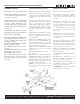
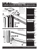
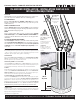
START FRAMING and SECURE SECOND POST
Insert the BOTTOM SUPPORT FRAME (G3) into post channels, rest-
ing on “L” brackets, use as a measuring stick to find the location for
the next post. Position post, pre-drill concrete or deck through base
plate using 3/8 in. x 4 in. bit. Secure with 3/8 in. x 4 in. anchor bolts or
screws (not included), tightly to base plate.
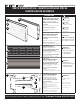
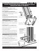
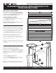
INFILL BOARDS and FINISH FRAMING
Insert boards according to desired design stacking order (PAGE 6). In-
sert the TOP BOARD FRAME CAP (G2), tap down with RUBBER MALLET to
secure. Insert “L” bracket, secure with self-tapping screw.
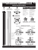
SECURE and FINISH POST INSTALL
Insert CHANNEL COVERS (H1) into unused FRONT CHANNEL slots. Place
POST CAP (H2) onto top of post.
REPEAT STEPS ABOVE FOR REST OF FENCE keeping in mind the loca-
tion of your gate.
COMMENCEZ LA CHARPENTE et FIXEZ LE DEUXIÈME POTEAU
Insérez LA STRUCTURE DE SUPPORT DU BAS (G3) dans les canaux du
poteau, reposant sur les équerres « L », utilisez comme bâton de
mesure pour trouver l’emplacement du prochain poteau. Placez le
poteau, prépercez le béton ou la terrasse au travers de la plaque de
base en utilisant une mèche de 1,57 cm x 10,16 cm. Fixez fermement à
la plaque de base avec des boulons ou des vis à ancrage de 1,57 cm
x 10,16 cm (non inclus).
INSÉREZ LES PANNEAUX et FINISSEZ LA STRUCTURE
Insérez les panneaux selon l’ordre de superposition du modèle
voulu (PAGE 6). Insérez la FINITION DE STRUCTURE DU PANNEAU
SUPÉRIEUR (G2), tapez avec un MAILLET EN CAOUTCHOUC pour fixer.
Insérez l’équerre « L », fixez avec une vis autotaraudeuse.
FIXEZ ET FINISSEZ L’INSTALLATION DU POTEAU
Insérez les COUVERTURES DE CANAL (H1) dans les fentes des CANAUX
AVANT non utilisées. Placez le CAPUCHON DE POTEAU (H2) dans le des-
sus du poteau.
RÉPÉTEZ LES ÉTAPES CI-DESSUS POUR LE RESTE DE LA CLÔTURE, en
gardant à l’esprit l’emplacement de votre porte.
ENSABLE y COLOCACIÓN DEL SEGUNDO POSTE
Inserte la ESTRUCTURA DE APOYO INFERIOR (G3) en los canales del
poste, sobre los soportes “L”; con una vara de medir determine la
ubicación del siguiente poste. Ubique el poste, taladre previamente
el concreto o el piso a través de la placa base con una broca de 3/8”
x 4”. Fije firmemente a la placa base con tornillos de anclaje de 3/8”
x 4” (no incluidos).
ENTABLADO y TERMINACIÓN DEL ENSABLE
Inserte las tablas en orden, según el diseño deseado (PÁGINA 6).
Inserte la TERMINACIÓN DE ESTRUCTURA SUPERIOR (G2) y afirme
martillando con un MAZO DE GOMA. Inserte el soporte “L”, fije con
el tornillo autorroscante.
(Continúa en la página 19)
G3
G2
G2
G1
72 in. on center
1,83 m au centre
1,83 m al centro
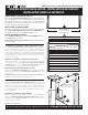
SURFACE MOUNT INSTALLATION • INSTALLATION EN SURFACE
INSTALACIÓN SOBRE LA SUPERFICIE
cut from extra (H1)
Pièce découpée (H1)
Cortar una pieza de (H1)