Pub.
Pub. #OM17-MSP3 MSP3 SoilViewer Version 2.46 Sensor DataLogger Version 1.00 Section 1 Warranty Veris Technologies warrants this product to be free of defects in materials and workmanship for a period of one (1) year from the date of delivery to the purchaser. Veris Technologies will repair or replace any product returned to Salina, Kansas, which appears upon inspection to be defective in materials or workmanship.
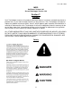
Pub. #OM17-MSP3 Important! Read the following SAFETY PROCEDURES before operating the Veris system: • Read and understand all instructions on safety decals • Escaping fluid under pressure can penetrate the skin causing serious injury. Avoid the hazard by relieving pressure before disconnecting hydraulic lines. Use a piece of paper or card-board, NOT BODY PARTS, to check for suspected leaks. • Wear protective gloves and safety glasses or goggles when working with hydraulic and highpressure wash systems.
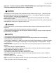
Pub. #OM17-MSP3 Excess speed, especially when turning could cause overturning. Never pull units faster than 15 km/hr. Use caution when working on implement. Coulter disks are sharp and may causes cuts. Don’t allow anyone to climb or ride on implement The vehicle that pulls the Veris unit thru the field will get hot! There is a chance that this heat can cause field fires in stubble fields.
Pub. #OM17-MSP3 Keep safety chain installed Install jack before unhitching; do not drop unit on foot FCC NOTE This equipment has been tested and found to comply with the limits for a Class A digital device, pursuant to Part 15 of the FCC Rules. These limits are designed to provide reasonable protection against harmful interference when the equipment is operated in a commercial environment.
Pub. #OM17-MSP3 EUROPEAN DECLARATION OF CONFORMITY Veris Technologies, Inc., located at 601 N. Broadway in Salina Kansas, certifies that the product: Veris MSP3 is in conformity with the following directive and standards: Machinery Directive 2006/42/EC--1st Edition—December 2009 Electromagnetic Compatibility 2004/108/EC —December 2004 EN55022 – Measuring Radiated Emissions The Technical File is maintained at: Veris Technologies, Inc. 601 N.
Pub. #OM17-MSP3 Statement of Use Intended use of the Veris MSP3 model The Veris MSP3 Soil EC, Organic Matter, and pH Mapping System collects geo-referenced soil electrical conductivity (EC), soil reflectance, and soil pH measurements as it is pulled across a field by a tractor. An electronic device called the Soil EC Surveyor, powered by vehicle’s 12V DC electrical system, generates a small electrical current, which is transferred into the soil through a pair of rolling electrode coulter disks.
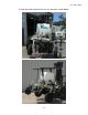
Pub. #OM17-MSP3 MSP3 Lifting Points Below are the recommended lifting points for the unit. Using two straps you can safely lift the unit. Make sure the straps used to lift are rated greater than 1200 lbs. Fork extensions maybe required to lift. Always stay clear when lifting the unit.
Pub. #OM17-MSP3 If lifting from front or back of the unit, use the points shown below.
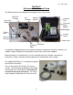
Pub. #OM17-MSP3 Section 2 Electronics Overview and Set-up The MSP3 electronics kit and optional DataLogger kit are shown below. MSP3 EC Test Box pH Simulator Mounting Bracket Protective Case USB Serial Adapter Three-way power adapter DataLogger OM test load SD card reader MSP3 EC test load Power Cord Figure 1a MSP3 electronics kit OM Reference Block Figure 1b MSP3 DataLogger kit SoilViewer Use protective shipping/storage case to protect electronics components whenever electronics are shipped.
Pub. #OM17-MSP3 Figure 3 DataLogger (rear) Reset button: Can be used to reboot DataLogger EC: Serial cable from EC/OM controller attaches here. OM/pH: Serial cable from pH controller attaches here. Alarm Vol: Used to adjust volume of auditory alarm Power port: The Sensor DataLogger is shipped with an accessory power cord. If an alternative connection is desired, make sure that the unit is properly connected to a power connection that is not controlled by the ignition switch.
Pub. #OM17-MSP3 The OpticMapper Controller is mounted on the implement, and can remain on the implement due to weatherproofing.
Pub. #OM17-MSP3 Electronic Configurations Datalogger – Attach the OpticMapper/EC Controller communication cable to the EC port on the Datalogger, then the communication cable from the pH Controller to the pH port. Connect EC signal cable, GPS, and power cords to the OM/EC controller. Figure 9 Soilveiwer – Connect both communication cables from OpticMapper/EC Controller and from the pH Controller to Laptop using the supplied USB to Serial converters.
Pub. #OM17-MSP3 SoilViewer Software Setup The Veris SoilViewer software will automatically run the setup once the CD is inserted into the computer. If not the installation can be manually started by double clicking on the setup.exe located on the CD. Click Next to continue through installation Figure 11 Once the CD has begun select the installation directory and click Next Figure 12 Next two license agreements will need to be accepted before continuing.
Pub.
Pub. #OM17-MSP3 Section 3 Implement Overview and Set-up Figure 1 MSP3 with EC, OM, and pH sensor modules Pinch point hazard: to prevent injury, stand clear when raising or lowering any part of the Veris MSP3. Install all transport locks before transporting or working underneath. Always use the service stands when working underneath the MSP3.
Pub. #OM17-MSP3 12 Volt Power and Hydraulics Set-up If the unit has been crated and delivered via closed-van commercial freight, the tongue (if equipped) may need to be installed prior to use. Prior to operating the implement for the first time, it is important to check all fasteners – some may have loosened during shipment. Route cables and hydraulic hoses along tongue and through hose guide. Tie-strap securely. Connect electrical cables to battery.
Pub. #OM17-MSP3 Flow control settings: Open center hydraulic systems 1) 2) 3) 4) Set poppet valve in “up” raised position, this allows flow back to tank Set engine at field rpm Set pH controller to “Manual” and run sampling shoe up and down, timing the cycle time. If sampler raises in approximately 1.5 -2 seconds, leave flow control as is, if not, adjust control arm upward or downward to achieve desired speed. Closed center hydraulic systems 1) Set poppet valve in down position.
Pub.
Pub. #OM17-MSP3 Remove pH electrodes from individual storage containers and fill soaker solution cup with soaker solution. Install soaker solution cup on electrode holder. Loosen plastic set screws on electrode holder and insert pH electrodes into electrode holder. Re-tighten set screws finger tight and lock in place with lock nuts. Do not overtighten set screws or electrode damage may occur.
Pub. #OM17-MSP3 Section 4 Field Operations: DataLogger: OM and pH System Checks Sensor DataLogger display readings Here are the display readings shown when operating the Sensor DataLogger: Starting up… Figure 1 The unit is ready to operate. The DataLogger is informing you of the firmware version its programmable interface chip (PIC) contains. Press any of the four keys, and the next screen will appear: Figure 2 For Mapping, press the #1 key. For OM System check press the #2 key (page 4-4).
Pub. #OM17-MSP3 If memory card was not inserted during boot-up, the following screen will appear: Figure 5 Install card and re-start DataLogger. NEVER REMOVE CARD WHILE LOGGING DATA. This is the Data Acquisition screen with GPS status (note:GPS status will blink every second when engaged to show the OM readings): Figure 6 GPS status: may read GPS, DGPS, RTK, or None. If None, no GPS signal is received and no data will be recorded.
Pub. #OM17-MSP3 There are warning signals programmed into the Veris DataLogger to warn the operator that data is not being recorded, so that corrective action can be taken. If data is not being recorded, a warning alarm will sound, and the portion of the screen text that is missing information will blink. For example, if the DGPS isn’t being received (or the NMEA string containing speed) the Lat/Long text will blink. If EC values are negative, they will blink.
Pub. #OM17-MSP3 Press #3 to continue with OM System check: Figure 11 Figure 12 If the window is clean and in good condition (see 4-8), attach the dark side of the Reference to the sensor. (Figure 12) Press any key to continue: Figure 13 After the readings have settled the next screen will appear: Figure 14 Turn the Reference block over and attach the light side of the Reference to the sensor.
Pub. #OM17-MSP3 After the light reference has been read, the following will appear: Figure 16 The reference data has now been stored. Once the system is restarted it is ready to start mapping. *NOTE: To ensure system is operating correctly always run a system check before mapping a field. There should be a difference of 100 or greater from dark reference to light reference for each wavelength.
Pub. #OM17-MSP3 The instrument will prompt for the electrodes to be inserted into pH buffer 4 solution; Slide cup with pH 4 buffer solution onto electrode holder. Press 1 to continue with calibration or 2 to exit. Tips: Don’t overfill solution. Cup only needs enough solution to immerse electrode tip and face. Don’t reuse solutions.
Pub. #OM17-MSP3 On the DataLogger, press 1 to continue with calibration. The DataLogger will read the electrodes for 10 seconds, displaying the output. After 10 seconds, the instrument will display the final pH reading and offer the options to 1) Accept pH 7 buffer readings; 2) Redo pH buffer 7 readings; or 3) Exit pH electrode calibration. If the readings are satisfactory, log pH 7 reading and press 1; if the readings are suspect, press 2 to return to pH 7 calibration step.
Pub. #OM17-MSP3 pH Controller Set-up After calibration, you may wish to change the pH Controller default parameters. Enter menu option 2) pHsetup Figure 26 Enter menu option2) Controller setup Figure 27 Figure 28 Sampling time is the duration that the sampler assembly is in the soil. Typically 2 seconds is adequate. In soil conditions that do not produce a firm core, this time may need to be set at 3 seconds in order to allow soil to begin flowing through cutting shoe.
Pub. #OM17-MSP3 Figure 30 Select the type of water you are using to clean the electrodes between samples. The available types are TAP, RO (reverse osmosis), or DI (de-ionized). Press 1 or 2 to cycle through the water types, press 3 to continue to the next screen. Tip: If you don’t want a baseline wash performed every 40 cycles, use RO setting rather than Tap or DI (regardless of actual water being used). Figure 31 Turning on the extra wash option will add 1.5 seconds of cleaning per cycle.
Pub.
Pub. #OM17-MSP3 The EC OM pH-MSP3 Mapping software will automatically detect which ports the Veris OpticMapper /EC Controller and pH Controller are connected to, and begin communicating. If either is not detected, the software will wait 45 seconds for the connection of the electronics and search again; this will repeat until both instruments are connected. If the electronics are not found, unplug the serial or USB cables and reconnect them to the PC.
Pub. #OM17-MSP3 SoilViewer OM System Check The OM System check ensures the optical sensor and controller are functioning properly. By using the light and dark reference block the range of the sensor can be determined. For proper operation the range from the dark to light side for the red and IR readings must be at least 100. If it is not that may indicate a broken wearplate, inadequte power, or damaged sensor. Run the system check before mapping each field to ensure proper operation.
Pub. #OM17-MSP3 pH System Check: Calibrating pH electrodes Click on Calibrate ISE’s or press F1 Figure 39 You will be asked if you want to continue the calibration or restore ideal settings. Figure 40 Figure 41 You will be asked for the ID of the electrode connected to channel 1. You may want to add an ID name or number to the electrodes, for your own tracking purposes. Insert the name or number then press OK to continue.
Pub. #OM17-MSP3 The software will prompt for the electrodes to be inserted into pH buffer 4 solution; Slide cup with pH 4 buffer solution onto electrode holder. Press 1 to continue with calibration or 2 to exit. Tips: Don’t overfill solution. Cup only needs enough solution to immerse electrode tip and face. Don’t reuse solutions.
Pub. #OM17-MSP3 After accepting the pH 4 buffer readings, the software will prompt for the electrodes to be inserted into pH 7 buffer solution. Remove the pH 4 buffer solution cup from the electrode holder. Rinse the electrodes, electrode holder, and solution cup using the manual wash for at least 10 seconds. Slide the pH buffer 7 solution cup onto the electrode holder. Figure 46 Press continue to proceed with the calibration. The software will read the electrodes for 10 seconds, displaying the output.
Pub. #OM17-MSP3 pH Controller Set-up After calibration, you may wish to change the pH Controller default parameters. Press Controller Setup or F3 and enter Setup menu. Figure 49 Figure 50 The pH sampler settings can be adjusted without exiting the current file. Additionally, a correction can be applied to each electrode’s pH shown on the screen. Occasionally, the pH readings shown on the screen may differ from those expected in the field.
Pub. #OM17-MSP3 Log time is the longest time in seconds the pH controller will wait for the pH readings to settle. The controller usually cycles before this maximum time is reached. The minimum setting for the log time is 20 seconds. Press the up or down arrows adjust the sample time. (Tip: use 20 seconds unless there is a special reason to allow a longer wait time) Select the type of water you are using to clean the electrodes between samples.
Pub. #OM17-MSP3 Field Operations—EC and OpticMapper Tools required for Field Operation adjustments -3/8”, 7/16”, 1/2” 9/16” 3/4” 15/16” wrench -9/16”, 3/4” 12point socket -3/8” ratchet -Ohm meter Checking Electrical Signal Continuity and Electrode Isolation It is recommended that you perform the Electrical Signal Continuity and Electrode Isolation test procedure before first field use (see Maintenance and Service Procedures 1 and 2).
Pub. #OM17-MSP3 Adjustable Wing Extensions This feature allows the re-positioning of the electrodes to fit various bed and crop configurations. Adjustment is made by loosening the jam nuts and set screws located on the lower front of each side of the toolbar, adjusting the toolbar wing extensions, and re-tightening the set screws. Veris suggests setting the toolbars at either the maximum or minimum setting, not at a point in between.
Pub. #OM17-MSP3 3-point Adjustment Top Link Turn the top link (Figure 60) to adjust the tilt and level the unit. This is the optimal setting for all fields types. Extending the top link will cause the rear of the unit to move down. Shortening the top link will cause the inverse. Row Unit Adjustment Adjust side depth wheels on optical row unit to allow deeper or shallower mapping. Move T-handle (Figure 61) backward for deeper depth. Depth wheels should be snug, but freely moving, against the disks.
Pub. #OM17-MSP3 Coulter Adjustment Adjusting the coulter depth is accomplished by re-mounting the coulter blade in one of the six mounting holes arranged in a staggered pattern in the coulter bracket. Figure 64 Raise unit and lower service stands before working on coulters. Do not attempt to move blade when the current or new position causes it to contact the ground during the adjustment. Be careful around the front end of row units. Row cleaner tines and coulter blades may be sharp.
Pub. #OM17-MSP3 Speed Proper field operating speed depends on field condition. Because of the importance of consistent contact, the unit must not be allowed to bounce over rough fields at high speeds. Field Condition Field should be in a uniform state. Mapping after intensive primary tillage is not recommended. The soil must have a minimum of 20% available water, and cannot be frozen. If rocky conditions exist, slow down and make sure rock guards are in place.
Pub. #OM17-MSP3 To help insure the quality of your data, please follow these guidelines: 1. Generate and view maps frequently, especially prior to deleting data from Instrument. 2. Listen for auditory alarm from DataLogger, indicating data collection has been interrupted. 3. View DataLogger screen or SoilViewer map frequently during data collecting; watch for: Negative readings in the Shallow and Deep or excessive noise in the OpticMapper data.
Pub. #OM17-MSP3 OM Data Quality Check depth of sensor – Make a couple of trial passes to make sure the sensor is running at the proper depth. Recommended depth is 2-3 inches. Add weights or adjust down pressure on row unit if needed Also make sure the row unit side depth wheels and disks are rotating freely, and are clear of excess mud and crop residue. For row unit adjustments see page 4-22.
Pub. #OM17-MSP3 OpticMapper Wearplate Below is a comparision of two wearplates. The left is a brand new wearplate, and the right has about 2500 acres on it. Inspect the leading edge,shown below, as the steel wears the window can chip or crack. As this contiunes to wear it will eventually need replaced. Figure 67a & b Wearplates will wear differently in every type of soil, so check it often.
Pub. #OM17-MSP3 Field Operation—pH Manager Tools required for Field Operation adjustments -3/16” allen wrench -adjustable wrench: min. 10” (25 cm) length -3/4” socket and wrench -9/16” socket or wrench -15/16” wrench Pinch point hazard: to prevent injury, stand clear when raising or lowering any part of the MSP3. Install all transport locks before transporting or working underneath. Always use the serivce stands when working underneath the MSP3.
Pub. #OM17-MSP3 Manually Operating Wash and Cycling Functions After all cables and hydraulic hoses are connected, test power to unit by turning external pH controller power switch to on position. With control switch in manual position, run wash pump briefly. If water does not flow from jets within 10 seconds, disconnect quick couplers to help pumps prime. If water doesn’t spray, but pump is running, see Troubleshooting section for instructions on priming pump.
Pub. #OM17-MSP3 Three-point Mounted Units Raise sampling mechanism to full height. Begin depth adjustment process with shank in center position (pin in one of two center holes). Adjust ratchet jack so that coulters will penetrate 1-2” deep – 21” pin-to-pin is a good starting point Adjust three-point top link to level unit when in soil.
Pub. #OM17-MSP3 Once unit is level, lower sampling mechanism completely, drive forward 10-20’ (3-6 m) to create soil core. To measure depth of soil core being collected, brush away soil from cutting shoe. Measure from soil surface to top of cutting shoe. This is the depth of sampling. To increase sampling depth, shorten ratchet jack; to decrease sampling depth, lengthen ratchet jack. Releveling unit with adjustable top link may be required.
Pub. #OM17-MSP3 Adjust scraper bracket until cutting shoe clears scraper when sampler assembly is raised completely. Figure 75 2. Adjust electrode holder: with sampling mechanism raised completely, adjust electrode holder to provide ½” (1.2 cm) clearance between it and sampling trough. Turn crank to raise or lower electrode holder Figures 76a and 76b ½” (1.2 cm) clearance between electrode holder and trough liner 3.
Pub. #OM17-MSP3 When installing BNC cover, route electrode wires under box; center box on white pad, and tighten wingnut finger tight. Keep cover installed even when electrodes are removed. When wash jets are properly aligned, overspray is minimized and water bubbles out top of empty electrode holder as shown here. Figures 78a and 78b 4. Insert pH electrodes into electrode holder. Finger-tighten plastic screws. Install BNC cover on external controller to keep moisture out of BNC connectors.
Pub. #OM17-MSP3 7. Prox sensor: The prox sensor communicates the position of the sampler assembly to the external controller for automatic cycling functions. Adjust sensor to 1/4”- 3/8” (6-9 mm) gap. Cycle unit manually to insure that this gap is maintained throughout cycling range. Red LED light should light whenever prox sensor is near metal and not light when away from metal. To view LED light, shade ambient light from prox sensor and cycle sampler assembly manually.
Pub. #OM17-MSP3 Mapping with Veris Datalogger Connect EC signal cable and power cords to ports on rear of OpticMapper/EC Controller, connect the GPS to the GPS in of the OM Comm. cable, then connect the serial output of the OM Comm. to the EC port on the DataLogger. Attach the pH controller to the pH port on the datalogger.
Pub. #OM17-MSP3 This is the Data Acquisition screen with GPS status (note: GPS status will blink every second when engaged to show the OM readings): Figure 88 GPS status: may Ground speed read GPS, DGPS, (from GPS) in RTK, or None. If miles/hour None, no GPS signal is received and no data will be recorded. Shallow (S) and Deep (D) soil EC readings. If negative, no data will be recorded.
Pub. #OM17-MSP3 After washing (or immediately if RO was selected as the wash water type), the unit will continue cycling and display the following screen: Figure 91 “Cycling” means the sampler assembly is in the process of washing, and lowering for soil sampling. After a core has been collected and is being held against the electrodes, the status text will change to the following: Figure 92 The pH readings on the display show what each electrode is reading at every second.
Pub. #OM17-MSP3 The Veris MSP pH Manager uses two electrodes for optimal data quality. If there is a difference of 0.75 or greater between the final electrode readings, an audible alarm will beep, informing the operator of the erroneous reading. To pause the data collection process at any time (but keep the same file), press the 1 key. Once the sampling process has completed its cycle, it will disengage and the status text message will indicate disengaged (press 1 to start cycling again).
Pub. #OM17-MSP3 Mapping with SoilViewer Attach the pH serial communication cable to an available COM port on your computer. Connect EC signal cable and power cords to ports on rear of OpticMapper/EC Controller, connect the GPS to the GPS in of the OM Comm. cable, then connect the serial output of the OM Comm. to any available COM port on your computer using a standard serial cable.
Pub. #OM17-MSP3 The EC OM pH-MSP3 Mapping software will automatically detect which ports the Veris OpticMapper/EC Controller and pH Controller are connected to, and begin communicating, provided the power to the OpticMapper and pH is turned on. If either is not detected, the software will wait 45 seconds for the connection of the electronics and search again; this will repeat until both instruments are connected and powered on.
Status of pH controller; Green means the controller is engaged while Red means it is disengaged and will not automatically cycle Control used to change between EC arrays Shallow (Sh) and Deep (Dp) soil EC readings. If negative, no data is being saved. Ranges used to map pH values. Each color should have a unique range with Pub.associated #OM17-MSP3 it. These are user-defined ranges and can be changed at any time.
Pub. #OM17-MSP3 Press Engage to start pH sampler cycling. Figure 98 From this screen, pressing the Engage key or Enter as you drive forward will initiate the automatic sampling process. The software requires movement indicated by the GPS receiver in order to cycle. Speed must be detected within 5 seconds after pressing enter or the system will disengage.
Pub. #OM17-MSP3 “Cycling” means the sampler assembly is in the process of washing, and lowering for soil sampling. After a core has been collected and is being held against the electrodes, the status text will change to the following: Figure 101 The pH readings on the display show what each electrode is reading at every second. The sampler will hold the soil against the electrodes and continue to record pH until the readings settle.
Pub. #OM17-MSP3 If TAP or DI are selected as the wash water type, the water baseline process will be repeated every 40 cycles following the next engage press. If the pH during the cycling sequence does not get within 0.5 of the baseline pH, the computer speakers will beep and the pH labels will blink. This is to allow operator that the electrodes are not cleaning properly.
Pub.
Pub.
Pub. #OM17-MSP3 SECTION 5 Maintenance and Service Soil EC Rockshaft pivot points Each pivot (located at the left and right) contains an upper and lower grease zerk. Due to the limited motion of the rockshaft, these should be lubricated on 20-hour intervals. This may vary based on the number of times the unit is raised and lowered.
Pub. #OM17-MSP3 grease zerk Figure 3 Figure 4 Hubs --Use good quality wheel bearing or lithium grease for lubrication, but we suggest that you grease the hubs sparingly. Over-lubricating the hub will result in pre-mature seal failure, and an excessive amount of grease in the hub cap/commutator. On an interval of 150 hours, 1-2 strokes of grease should be sufficient. Pinch point hazard: to prevent injury, stand clear when raising or lowering any part of the Veris MSP3.
Pub. #OM17-MSP3 OpticMapper Row unit Setting Sensor Depth Refer to Figure 7 The “T” handle (1) sets sensing depth by limiting the how high the side depth gauge wheels ride relative to the opener disks. To adjust sensing depth, pull the “T” handle (1) up and back,move it forward or aft, and set it back in a different pair of holes in the scale. • For shallower sensing, move the “T” handle (1) forward. • For deeper sensing, move the “T” handle (1) back.
Pub. #OM17-MSP3 Side Gauge Wheel Adjustment Refer to Figure 10 and Figure 11 Disc-to-wheel angle and clearance ideally has the wheel just touching the disk when the wheel is raised to sensing depth (is up against the stop set by the “T” handle. The goal is to have both disks and wheels turn freely, but keep soil and trash from getting between them. These two adjustments interact with each other. Changing one requires at least checking the other.
Pub. #OM17-MSP3 • If wheel does not fall freely, loosen hex-head bolt (1) and slide wheel arm out just until wheel and arm move freely. Retighten hex-head bolt (1) according to grade: 1⁄2in Grade 5 bolt on 25 series, 75 ft-lbs (102 N-m). 1⁄2in Grade 8 bolt on 25 series, 110 ft-lbs (149 N-m). 6. Keep turning hex adjuster and moving wheel arm until the wheel is adjusted properly. When satisfied, tighten pivot bolt (2) to 110 ft-lbs (149 N-m).
Pub. #OM17-MSP3 Replacing Opening Disk 1. 2. 3. 4. Make a note of current Disk depth Remove the 5/8-11 x 4in bolt, lock washer and nut Replace disk with new disk. Reinstall disk to proper depth. Figure 16 Opening Disk lubrication The opening disks each have a grease zerk on them (right and left side). Due to the constant rotation, these should be lubricated on 80–hour intervals. Figure 17 Depth Gauge Wheels lubrication The depth gauge wheels have and upper and lower grease zerk at each pivot.
Pub. #OM17-MSP3 pH system Clean-up—ISE storage, wash If you are going to interrupt your pH mapping for 30 minutes or longer, clean off the electrodes and the electrode holder with the wash wand, and install the soaker solution container on the electrode holder. Replace soaker solution (Veris part #23395) weekly, or more frequently if it is diluted or dirty.
Pub.
Pub. #OM17-MSP3 Wash System If wash water develops algae, flush and fill tanks with tap water; clean any algae or other foreign matter out of tank using clean-out ball valve (right side). Set wash system ball valve (left side) to open position, allowing water to flow to pumps. Clean filter at least once per week of operation. Remove plug and turn on ball valve to clean.
Pub. #OM17-MSP3 Wear Item Replacement Inspect cutting shoe for wear and gouges, replace as needed. Knock old shoe off with punch and tap new shoe on, as shown here. TIP: Rotate cutting shoe to prolong wear life. knock worn shoe off from rear tap new shoe on with 2x4 Figures 24a and 24b Replace sampling trough liner, scraper cutting edge when wear is apparent. Closing disk Lubrication The closing disks each have a grease zerk on them (right and left side).
Pub. #OM17-MSP3 Section 6 Service and Troubleshooting Procedures EC data seem odd—jumpy, negatives, map doesn’t match known or expected soil types Perform Maintenance and Service Procedures #1-3. No GPS or DGPS on display Perform Maintenance and Service Procedure #5 DataLogger locks up -SD card not installed or not formatted. See Procedure #6 to format card. -Make sure the SD card is not a SDHC card.
Pub. #OM17-MSP3 Procedure #1: OM Signal Testing Perform this test daily or every 10 hours of data collection to ensure you are obtaining reliable data, and whenever EC data is questionable. The purpose of this test is to insure that the instrument is performing properly. The OpticMapper/EC Controller is shipped with an Instrument Test Load (Part No. 46403) that will enable you to quickly check the instrument to ensure that it is functioning properly.
Pub. #OM17-MSP3 Procedure #2: EC Signal Testing Perform this test daily or every 10 hours of data collection to ensure you are obtaining reliable data, and whenever EC data is questionable. The purpose of this test is to insure that the instrument is performing properly. The OpticMapper/EC controller is shipped with an Instrument Test Load (Part No. 49492) that will enable you to quickly check the instrument to ensure that it is functioning properly.
Pub. #OM17-MSP3 Procedure #3: Testing Electrical Continuity Perform this test daily or every 10 hours of data collection to ensure you are obtaining reliable data, and whenever EC data is questionable. The purpose of this test is to insure that each coulter-electrode has an uninterrupted signal path from the EC Surveyor to the disk blade. Think of each coulter-electrode and its wire path as a ‘channel’.
Pub. #OM17-MSP3 Signal extension cable (from implement) Figure 3.3 Firmly press one lead of the ohmmeter to the #1 coulter blade edge (left hand, standing behind the unit) and the other lead to the #1 terminal on the test box. Maintain firm pressure on the ohmmeter lead touching the disk blade. A reading of less than 2 ohms is normal. Rotate blade ¼ of a turn back and forth as you view the ohmmeter. Any jump in the readings above 2 ohms indicates a problem.
Procedure #4: Diagnosing and Correcting EC Signal Problems. Pub. #OM17-MSP3 Use this Troubleshooting tree to work through the system, locate the problem, and take corrective action. Figure 4.
Pub. #OM17-MSP3 Coulter Electrode FunctionsEach coulter electrode on the implement is part of a pair, and each pair has a distinct function. a) Coulters 1 & 6 are the Deep EC receptors. If you are seeing problems only with the “Deep” readings, focus on testing continuity on these two coulter-electrodes. b) Coulters 2 & 5 are the “charged” coulters that inject the voltage into the soil.
Pub. #OM17-MSP3 Figure 4.3 Testing cable at end of signal cable wiring harness Figures 4.4 ab. a. Separating sure-seal connector b. Testing terminal connector wire 4. If there is a >2 ohm reading in the signal cable harness or signal extension cable, visually inspect the wiring harness and cable extension for damage. If a visual inspection doesn’t reveal a problem, you will need to test continuity of the wiring harness and cable. You will need to ohm these cables out individually.
Pub. #OM17-MSP3 5. To ohm out the wiring harness, disconnect the serial cable extension from the implement and check continuity through the harness as shown in Figures 10a and 10b. While doing so, check the pins and the sockets of the 6-pin connector for corrosion and fit. If necessary spread the pins with a small screwdriver to tighten fit in sockets. 4 2 3 5 1 6 Figures 4.6 a and b.
Pub. #OM17-MSP3 hubcap commutator coulter spindle Figure 4.7 C. Testing Coulter-Electrode isolation If continuity tests show no excessive resistance on any channel, yet erratic soil EC readings continue, or if EC readings do not drop to –1 when unit is out of the soil, it is possible that the channels are not isolated. This could be the result of a pinched wiring cable, causing channels to short out.
Pub. #OM17-MSP3 2. Inspect nylon insulation slides under coulterelectrode mounting brackets. These nylon insulators may become worn or brittle, or may slip out from under mounting bracket. Repair and replace as necessary. Make sure that all electrode coulter Ubolts are properly tightened to clamp mounting bracket and insulation tightly to frame. Figure 4.9 3. Disconnect signal cable from instrument or front of frame.
Pub. #OM17-MSP3 Procedure #5 Spring Plunger adjustment and replacement The spring plungers are located in the center of each coulter electrode hub cap, and are vital to maintain good continuity through the coulter hub bearings. They are factory preset, and should not need routine adjustment. If a continuity test shows abnormally high resistance, the plungers should be checked.
Pub. #OM17-MSP3 Procedure: 1) Remove hub cap by turning clockwise with a pipe wrench or large adjustable wrench – these caps have left hand thread to prevent loosening during field rotation. 2) If plunger is frozen in cap, remove allen head set screw on top of plunger and apply penetrating oil on both sides of plunger. Let this stand for a few minutes and try to remove. If it will not back out with allen wrench, lock vise grips on the inside portion and turn out through inside of hub.
Pub. #OM17-MSP3 Procedure #6: Diagnosing GPS-related problems If you do not see a GPS, DGPS, or RTK in the upper left-hand corner of the EC Surveyor screen, you do not have GPS coming in, and no data will be sent out the serial port for logging. Figure 6.1 Insure your GPS receiver is powered and outputting only two NMEA strings GGA, and either VTG or RMC at a 1hz rate; 4800 baud, 8 data bits, no parity, 1 stop bit.
Pub. #OM17-MSP3 If it becomes necessary to send GPS data into your PC, you will use a program called HyperTerminal. This program is in all Windows software. It is designed to record serial data streaming into a serial or USB port on the computer. The purpose of this is two-fold: 1) it verifies whether your GPS and cables are delivering the proper messages, and 2) it give Veris Technologies support personnel a GPS data file to test. Here’s how to use HyperTerminal 1.
Pub. #OM17-MSP3 5. The program will then ask you for a phone number. Instead of entering a phone number, specify the proper serial port number. For example, if Com 1 of the laptop is being used, specify “Direct to Com 1” under “connect using:” at the bottom of the entry area. Figure 6.5 6. HyperTerminal will then display a configuration menu where you can specify 4800 bits per second, 8 data bits, no parity, 1 stop bit and no flow control. Figure 6.
Pub. #OM17-MSP3 7. At this point, upon clicking ok, legible strings of GPS data should begin appearing on the laptop screen. Here’s an example of a typical set of strings: $GPGGA,191528.00,3851.0333,N,09737.2342,W,2,08,1.3,372.7,M,27.3,M,10.0,0100*69 $GPRMC,191528.00,A,3851.0333,N,09737.2342,W,0.1,0.0,090998,6.3,E*48 8. If GPS data doesn’t appear, recheck the port and configuration settings to make sure they are correct.
Pub. #OM17-MSP3 Procedure #7: SD card formatting and firmware updates USING A VERIS SD CARD IN OTHER DEVICES CAN CAUSE FILE CORRUPTION. Insert a standard SD card (not SDHC type) into a SD card reader which connected to your computer. Open “My Computer” folder. Right click on the SD card icon, and select the “Format”. Figures 7.1 a and b. In the format window, click on the file system tab and select “FAT” not “FAT32”. Then press “Start”. When complete, remove the card.
Pub. #OM17-MSP3 Updating Data Logger Firmware 1. Shut off the power of the Data Logger. 2. Copy the firmware on the SD card. (firmware found at veristech.com software download site) 3. Put the SD card into the Data Logger. 4. Turn on the power of the Data Logger. 5. Press the RESET button on the rear panel and (1) key simultaneously. Figure 7.2 6. Hold the (1) key and release the RESET button. 7. If you can see the following messages, then release the (1) key. Figure 7.3 8.
Pub. #OM17-MSP3 9. Then you can see the following messages in sequence. Figures 7.4 a and b. 10. Do not shut off the power, but repeat from step 5 to 9 again. 11. Press the RESET button or shut off and turn back on the power. 12. Check the LCD display. If nothing shows up in the LCD, or if display doesn’t contain the new firmware version number, please repeat from step 1 to 11.
Pub. #OM17-MSP3 Procedure #8: Bearing Repair and Replacement The coulter electrode hubs operate in a significantly harsh environment, and annual inspection is of utmost importance. The double-lip seals are designed to keep grease in, and contaminates out, but they are the cause of practically all hub failures. It is advisable to disassemble, clean and repair annually.
Pub. #OM17-MSP3 Procedure #9 SoilViewer Troubleshooting OpticMapper or pH controller is not found Check to ensure the com which the EC Surveyor/OpticMapper is connected to is present under the device manager. To get to the device manager go to StartSettingsControl PanelSystem Click on the Hardware tab and then click on the device manager button. Click on the “+” sign next to Ports and make sure the port is listed here.
Pub. #OM17-MSP3 Procedure #10: Optical Wear plate and Side Wear plate replacement 1. Remove the bolts attaching the optical sensor assembly to the row unit. 2 2. Remove the hex screws attaching the side plates to the optical sensor. 3. To remove wear plate, unscrew the hex bolts on the top of the optical sensor as shown in figure 10.2 1 4. Now to replace the wear place, ensure the O-ring is seated in the o-ring grove as shown in figure 10.3. Figure 10.1 5.
Pub. #OM17-MSP3 Procedure #11 pH Module 1. Unit doesn’t cycle when “1” key is pressed (in Automatic Mode) -check to be sure you are in Data Acquisition mode—screen below: Figure 11.1 -check to be sure that external controller is in Automatic mode. If it isn’t, this screen will appear: Figure 11.2 -follow troubleshooting flow chart below and see related Procedures in Maintenance and Procedure Section Figure 11.
Pub. #OM17-MSP3 2. Functions Aren’t Working in Manual Mode -follow troubleshooting flow chart below and see related procedures in Maintenance and Service Procedure Section. Figure 11.4 1. Sampling mechanism locks up or mis-cycles -press “1” to disengage, turn external controller to Manual and check prox sensor adjustment (see Procedure #4 in Maintenance and Service Procedure Section.) -check DGPS signal -if status of sampler shows “Cycling” for long periods, set sampler shank to shallower position.
Pub. #OM17-MSP3 2. Wash system malfunctioning: no water being pumped -are there at least 10 gallons of water in tank? -are pumps running? If not, check electrical connections and 12 volt power to them -check pressure switch on pump—wiggle wire, disconnect and reconnect; direct wire if needed -is filter plugged? -is ball valve open? -disconnect quick couplers to help pumps prime 3. pH readings seem erroneous or won’t calibrate -Use pH simulator to test External Controller and Veris instrument.
Pub. #OM17-MSP3 6. pH electrodes are not being cleaned of soil adequately -check wash system in manual mode—are both pumps operating properly? -check alignment of wash jets -check wash function operation while in automatic mode -increase wash time in Controller set-up menu; this can be done either by selecting the extra wash option, by extending the cycle time to 3 seconds—or both. 7. Too many pH points are rejected -check electrodes and wash system for adequate cleaning -recalibrate the electrodes 10.
Pub. #OM17-MSP3 -Replace fuse F2 with supplied cylindrical fuse. Part #8496 -Check all power connections and check cables for damage before turning on pH controller. Power is turned on but only LEDs D1 and D2 are lit... -Turn off pH controller. -Remove cover from pH controller. -Replace fuse F1 with supplied miniature fuse. Part #22611 -Check all power connections and check cables for damage before turning on pH controller.
Pub. #OM17-MSP3 Procedure #12: Checking External Controller Power The Veris pH module requires a minimum of 12 volts at all times. 12 volts at the battery terminals is NOT sufficient power for the system to function, due to the significant current draw when the pumps and solenoids are engaged. Reduced voltage can be caused by corroded or dirty terminals, and an inadequately charged battery or failure in the charging system.
Pub. #OM17-MSP3 POWER (12V) FUSE 2 (10A) and its LED 12V C 5V FUSE 1 (500 mA) and its LED Figure 12.2 External Controller circuit board (metal cover removed) 2. Turn off power to External Controller, remove clear lid and remove and replace any fuse that has failed. 3. Check voltage with a digital voltmeter at power supply connection All functions must be engaged during this test.
Pub. #OM17-MSP3 If voltage at power connector drops below 12 volts during this test: a) clean battery terminals b) check disconnect contacts c) hook power leads directly to battery—not through tractor power port d) charge battery 4. Check voltage at power cable (Figure 12.4). If 12V at cable but not on circuit board—call Veris Service Dept. Figure 12.
Pub. #OM17-MSP3 Procedure #13: Troubleshooting Sampler Cylinder Hydraulics The Veris pH module uses electro-hydraulics to perform the cycling functions. If the sampling shoe hydraulic cylinder is not functioning properly, the cause of the problem must be traced to either the electronic or the hydraulic side. This Procedure will guide you through the steps necessary to identify the problem when the sampler cylinder in manual mode is not moving or only moves in one direction.
Pub. #OM17-MSP3 SOLENOID LED’s UP 12V C 5V DOWN Figure 13.2 External Controller circuit board (metal cover removed) 3. Test voltage coming out of External Controller to solenoids. Disconnect the weather-pack connectors in line from Controller to the solenoids. Using a digital voltmeter set to read voltage, insert leads into connector coming from Controller. Activate manual raise-lower switch and read voltage. (Figure 13.3) Voltage should be 12 volts. Figure 13.
Pub. #OM17-MSP3 4. Test continuity of coil. With voltmeter set to ohms (resistance), insert both leads into the weatherpack connector leading to each solenoid. Start at the jumper wire (at first connection from external controller) and move to connector at solenoid. This tests the continuity of the signal through the coil. You should have continuity if the coil is working. Test both solenoids. Figure 13.4 Testing continuity of solenoid coil (at weather-pack connector on jumper-wire. 5.
Pub. #OM17-MSP3 Procedure #14: Troubleshooting Communication Problem Communication between the Veris Instrument and the External Controller is required for the system to initialize (sampler cylinder moves to neutral), and function. A communication failure between these components may be expressed as INIT ERR (initialization error) or COMM ERR (communication error). Follow flow chart below to address problems in their logical sequence. Figure 14.
Pub. #OM17-MSP3 Figure 14.2 Inspecting pins on communication cable 2. Testing continuity on communication cable. a) Unplug the communication cable from the DataLogger or PC. b) Bring both ends of the communication cable close enough together to reach with a voltmeter. c) Set your voltmeter to resistance (or continuity). Check continuity between the following pins: (Figure 3.
Pub. #OM17-MSP3 3. Testing continuity from the circuit board through the communication cable a) Remove the steel cover and unscrew the plastic lid from the external Controller. b) Look for the brown Molex 3-pin connector circled in Figure 14.4. The color sequence (left->right) should be white-green-black. CAREFULLY wiggle each wire to check for a loose connection. c) Check continuity between the following pins: Figure 14.
Pub. #OM17-MSP3 4. Testing that the external controller is receiving/acknowledging the command sent to it by the DataLogger or PC. a) Turn on the external pH Controller. b) Open up a HyperTerminal session on a PC: Click Start►Programs►Accessories►Communications►HyperTerminal. A new session of Hyper Terminal should open. In the box labeled “Connect using___” you will need to select the Com port you will be using. (on Windows 2000 and older: Under the Call menu, click Disconnect.
Pub. #OM17-MSP3 5. Testing that the instrument is sending the proper command to the external controller. a) Connect the DataLogger or PC to the PC using a serial cable (you will need a null modem and may need a gender changer). Turn on the DataLogger or PC and enter data acquisition. The data in Hyper Terminal should look like this $U♥♦Ç$U♥♦Ç The important letter above is the ‘U’, but the data coming up should match this character-for-character. The ‘U’ is the letter the pH Controller is looking for.
Pub. #OM17-MSP3 Procedure #15: Troubleshooting Prox Sensor The prox sensor, located on the left of the sampler shoe parallel linkage arm, is critical to the machine’s function. It informs the external controller of the sampler’s position, which allows the controller to move the sampler to the next position in the sampling/measuring sequence. If the prox sensor is not functioning properly, the entire operation will be affected. The problem may be with the Prox sensor itself or with its adjustment.
Pub. #OM17-MSP3 2. Adjust prox sensor gap if needed. Adjust sensor to 1/4”- 3/8” (6-9 mm) gap (Figure 15.3). Cycle unit manually to insure that this gap is maintained throughout cycling range. 1/4 to 3/8” gap (6-9 mm) Figure15.3 Prox sensor gap 3. Adjust prox sensor height if needed. Loosen bolt holding prox sensor arm and rotate to change height of prox sensor (Figure 15.4). Adjust prox sensor height with sampler shoe completely raised.
Pub. #OM17-MSP3 4. Check voltage to prox sensor if needed. Disconnect sure-seal connector from external controller to prox sensor. Check for 12V voltage on socket #1 and pin #3 from external controller, with power to external controller turned on (Figure 15.5). Do not short across voltmeter leads. Figure 15.