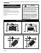
INSTALLER / CONSUMER SAFETY INFORMATION PLEASE READ THIS MANUAL BEFORE INSTALLING AND USING APPLIANCE. WARNING! IF THE INFORMATION IN THIS MANUAL IS NOT FOLLOWED EXACTLY, A FIRE OR EXPLOSION MAY RESULT CAUSING PROPERTY DAMAGE, PERSONAL INJURY OR LOSS OF LIFE. Pinnacle & Stardance Direct Vent, Rear Vent Gas Heater Models: 2950, 2951, 2995, 2996, 2997 & 2998 — Do not store or use gasoline or other flammable vapors and liquids in the vicinity of this or any other appliance.
Vermont Castings Pinnacle & Stardance Direct Vent - Rear Vent Gas Heaters Table of Contents PLEASE READ THE INSTALLATION & OPERATING INSTRUCTIONS BEFORE USING APPLIANCE. Thank you and congratulations on your purchase of a Vermont Castings stove. IMPORTANT: Read all instructions and warnings carefully before starting installation. Failure to follow these instructions may result in a possible fire hazard and will void the warranty. Installation & Operating Instructions Stove Dimensions ......................
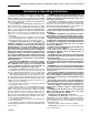
Vermont Castings Pinnacle & Stardance Direct Vent - Rear Vent Gas Heaters Installation & Operating Instructions The Pinnacle (PDV20) and Stardance (SDVR) Direct Vent Room Heater, Model Nos. 2950, 2951, 2995, 2996, 2997 and 2998, are vented gas appliance listed to ANSI Standard Z21.88b-2001 and CSA-2.33b-2001 for Vented Room Heaters, and CSA 2.17-M91, Gas-Fired Appliances For Use at High Altitudes.
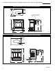
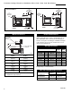
Vermont Castings Pinnacle & Stardance Direct Vent - Rear Vent Gas Heaters Stove Dimensions - Pinnacle Direct Vent Gas Heater 5" (140mm) 17" (432mm) Flue Transition Connector (For fireplace installation only) 24³⁄₈" (619mm) 25¹⁄₄" (641mm) 22³⁄₈" (568mm) 16³⁄₈" (400mm) 26¹⁄₂" (673mm) 3457 Fig. 1 PDV20 dimensions. Stove Dimensions - Stardance Direct Vent Gas Heater 7" (178mm) CL Valve Inlet 26³⁄₄" (680mm) 26" (660mm) 24" (610mm) Valve Inlet CL 3" (76mm) 25" (635mm) 14" (356mm) 3457 Fig.
Vermont Castings Pinnacle & Stardance Direct Vent - Rear Vent Gas Heaters Clearance Requirements WARNING: Minimum Clearances to Combustible Materials Measure side clearances as shown in Figures 3, 4 and 5 from the outer edge of the cast iron stove top. Measure rear clearances from the outermost surface of the steel rear skirt. The PDV20 and SDVR heaters are approved for installation into an alcove constructed of combustible materials to the dimensions and clearances shown on the next page.
Vermont Castings Pinnacle & Stardance Direct Vent - Rear Vent Gas Heaters 9" (230mm) Max. Mantel Width Alcove Installation 6" (150mm) Sidewall/ Trim See Fig. 6 6" (150mm) Sidewall/ Trim 2¹⁄₂" (63mm) Rear Wall PDV20 ST381 9" (230mm) Max. Mantel Width See Fig. 6 SDVR 2¹⁄₂" (63mm) Rear Wall ST381a Fig. 5 Alcove installation. Hearth Requirements Mantel Clearances The PDV20 and SDVR Heaters must be installed on rigid flooring.
Vermont Castings Pinnacle & Stardance Direct Vent - Rear Vent Gas Heaters Pinnacle / Stardance Direct Vent / Rear Vent Certified to: ANSI Z21.88b-2001 / CSA Z2.33b-2001 Vented Gas Fireplace Heaters The installation must conform with local codes or, in the absence of local codes, with the National Fuel Gas Code, ANSI Z223.1 - latest edition. (EXCEPTION: Do not derate this appliance for altitude. Maintain the manifold pressure at 3.5” w.c. for Natural Gas and 10” w.c. for Propane.
Vermont Castings Pinnacle & Stardance Direct Vent - Rear Vent Gas Heaters Vertical Termination Vent Termination Clearances A vertical vent system must terminate no less than 8' (2.44m) and no more than 40’ (12m) above the appliance flue collar. A 2¹⁄₄" restrictor plate (supplied) must be used (where specified) in all vertically terminated vent systems. NOTE: The restrictor plate supplied with the vertical termination should be discarded.
Vermont Castings Pinnacle & Stardance Direct Vent - Rear Vent Gas Heaters Vent Termination Clearances Your stove is approved to be vented either through the side wall, or vertical through the roof. • Vermont Castings, Majestic Products does not require any opening for inspection of vent pipe. • Only Vermont Castings, Majestic Products venting components specifically approved and labelled for this stove may be used.
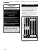
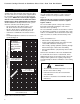
Vermont Castings Pinnacle & Stardance Direct Vent - Rear Vent Gas Heaters General Venting Information - Termination Location INSIDE CORNER DETAIL G V H A D V N N E V B C V L B Fixed Closed Ope F B V Operable rab V le V Fixed Closed G V B B B V J X I A V VENT TERMINATION M G V K X V A X AIR SUPPLY INLET AREA WHERE TERMINAL IS NOT PERMITTED CFM145a Canadian Installations1 A = Clearance above grade, veranda, porch, deck, or balcony B = Clearance to window or door that ma
Vermont Castings Pinnacle & Stardance Direct Vent - Rear Vent Gas Heaters Termination Clearances Termination clearances for buildings with combustible and noncombustible exteriors.
Vermont Castings Pinnacle & Stardance Direct Vent - Rear Vent Gas Heaters Vent Components The following kits are available to meet the needs of most installations. All pipe has a 7" outer diameter and includes a 4" diameter inner section. A (CG) designation indicates the part is finished in Charcoal Gray paint. Consult your dealer about other vent parts that may be appropriate to complete the installation.
Vermont Castings Pinnacle & Stardance Direct Vent - Rear Vent Gas Heaters Assembly Procedures WARNING Failure to position the parts in accordance with these diagrams or failure to use only parts specifically approved for use with this heater may result in property damage or personal injury. This heater and components are heavy. Have help available for assembly. Tool/Materials Required NOTE: Verify the two relief doors (located on top of the firebox) are properly seated on the gasket.
Vermont Castings Pinnacle & Stardance Direct Vent - Rear Vent Gas Heaters Heater Shell Assembly PDV20 B A Unpack the cast iron stove shell parts from the shipping carton. Inspect each part for shipping damage and set them aside on a protective surface. Porcelain enamelled surfaces are fragile. Handle porcelain enamelled castings gently. 1. Use only the rear shroud supplied with this firebox.
Vermont Castings Pinnacle & Stardance Direct Vent - Rear Vent Gas Heaters Install the Firebox Install Optional Fan Kit #2960/FK28 NOTE: Dry fit the Starter Pipe and first vent pipe sections to the flue collar to align and drill pilot holes as necessary, while the firebox is on the shipping pallet. You will not be able to drill holes after the firebox is installed.
Vermont Castings Pinnacle & Stardance Direct Vent - Rear Vent Gas Heaters Cut pad to size and locate as needed FK105 Fig. 21 Vibration dampening pad location. ST241 Fig. 19 Correct position of fan skirt installation. Blower Wiring Diagram Fan Assembly No. 000-2960 / FK28 BLK BLK SNAPSTAT WHT GRN BLK WHT 4. The rheostat control switch attaches to the left side of the valve bracket at the front of the stove. (Fig. 20) • Remove the plug from the rheostat bracket.
Vermont Castings Pinnacle & Stardance Direct Vent - Rear Vent Gas Heaters 9³⁄₈” W x 10³⁄₈” H Wall Opening Phillips Screws ST396 Fig. 23 Apply sealant to the starter pipe, and fasten to stove with Phillips screws. 2. Locate the vent opening on the wall. Refer to Figures 24, 25 & 26 to determine the top of the opening centerline. It may be necessary to first position the stove and measure to find the hole location.
Vermont Castings Pinnacle & Stardance Direct Vent - Rear Vent Gas Heaters • Side Wall Terminations: Dry fit the inner elbow with the vertical inner vent and confirm the centerline alignment with the wall thimble opening. 4. Attach the elbow to the starter pipe. • Run a bead of sealant about 1/2” from end of the starter pipe and attach the assembly to the stove using three 1/4-20 x 3/8” Phillips screws provided in the parts bag. (Fig. 29) 59¹⁄₄" (1505mm) 5.
Vermont Castings Pinnacle & Stardance Direct Vent - Rear Vent Gas Heaters Side Wall Termination Assembly 1. Locate the vent opening on the wall. Refer to Figures 27 & 28, to determine the minimum centerline of wall opening. It may be necessary to first position the stove and measure to find the hole location. Depending on whether the wall is made of combustible materials, cut the opening to the size shown in Figure 31. Combustible wall openings must be framed as shown in Figure 31. 2.
Vermont Castings Pinnacle & Stardance Direct Vent - Rear Vent Gas Heaters 3. 4. X 5. ST215 Fig. 34 Measure the horizontal length. 6. Trim Collar Wall Sleeve Wall Screws Snorkel and Anchors Termination Cap Wall Plate ST216 (400mm) below the base of the snorkel. Install a window well (not supplied). Refill the hole with 12” (305mm) of coarse gravel and maintain a clearance of at least 4” (100mm) below the snorkel. (Fig. 37) Install the vent system as described on pages 19-21.
Vermont Castings Pinnacle & Stardance Direct Vent - Rear Vent Gas Heaters Vertical (Through the Roof) Vent Assembly NOTE: All vertically terminated installations must, where specified, use the 2¹⁄₄” restrictor plate, to comply with Vertical Termination Window (Fig. 8, Page 9), included in the hardware bag. The plate must be installed within the firebox inner flue collar to insure a proper air/fuel ration is maintained in an appliance vented through the roof. (Fig. 39) 8.
Vermont Castings Pinnacle & Stardance Direct Vent - Rear Vent Gas Heaters Vertical Through Existing Chimney The heater must be vented to the outdoors through an existing masonry or prefabricated fireplace chimney system through the roof. The heater is approved to be vented to the outdoors through any solid-fuel fireplace chimney that has been constructed or installed in accordance with the national, Provincial/State and local building codes and is constructed of noncombustible materials.
Vermont Castings Pinnacle & Stardance Direct Vent - Rear Vent Gas Heaters Fireplace Installation Requirements - PDV20 Transition Connector 22³⁄₈" (568mm) 24³⁄₈" (619mm) 25¹⁄₄" (641mm) Transition Connector 24³⁄₈" (619mm) 15³⁄₄" (400mm) 18³⁄₄" (476mm) ST379 ST380 Fig. 43 PDV20 minimum lintel height for flush or forward placement.
Vermont Castings Pinnacle & Stardance Direct Vent - Rear Vent Gas Heaters Fireplace Installation Requirements - SDVR Transition Connector Transition Connector 26" (660mm) 26" (660mm) 20¹⁄₂" (521mm) 16" (406mm) ST380a ST379a Fig. 45 SDVR minimum lintel height for flush or forward placement.
Vermont Castings Pinnacle & Stardance Direct Vent - Rear Vent Gas Heaters Connect the Gas Supply Line Check the rating plate attached by a steel cable to the firebox, to confirm that you have the appropriate firebox for the type of fuel to be used. The PDV20 and SDVR may be converted from one gas to another using the appropriate Fuel Conversion Kit listed on page 36.
Vermont Castings Pinnacle & Stardance Direct Vent - Rear Vent Gas Heaters Switch Assembly Existing Holes Screws ST315 Bottom Tabs Engage Notch in Base Fig. 47 Attach switch assembly to rear shroud. ST407 Fig. 49 Install Stove Front. TH 2. If you are installing optional Warming Shelves, do so now, according to the instructions supplied with that kit. PILOT ADJ TPTH TP 3. Install the Top Plate. The upper edges of the side plates should seat into the channel on the underside of the Top. (Fig.
Vermont Castings Pinnacle & Stardance Direct Vent - Rear Vent Gas Heaters Install the Log Set Models 2950, 2951 Remove the logs from their packaging, and inspect each piece for damage. DO NOT INSTALL DAMAGED LOGS. 1. Install the rear log by engaging it with the pins on the sheet metal shelf at the back of the firebox. (Fig. 53) Models 2995, 2996, 2997, 2998 2. Install the left and right middle logs by engaging holes on their bottoms with pins on the burner brackets. (Fig. 53) 1.
Vermont Castings Pinnacle & Stardance Direct Vent - Rear Vent Gas Heaters Operation Piezo Ignitor Button TH TP PILOT ADJ TPTH T O OFF ON P IL I O H Regulator Control Knob Clockwise to Open Pressure Tap L The Stardance may be operated with the solid front plate in place or with the operable door front plate in place with the doors open or closed. To open the front doors, insert the handle into the door latch stub and turn it to the left and up. (Fig.
Vermont Castings Pinnacle & Stardance Direct Vent - Rear Vent Gas Heaters ST233 Fig. 60 Correct pilot flame pattern. PSE Pilot. Red Glow LG140a Fig. 63 Correct burner flame pattern. ST233a Fig. 61 Correct pilot flame Models 2950, 2951. Red Glow LG155 Fig. 64 Correct burner flame pattern for Models 2950, 2951. CO105c Fig. 62 Correct pilot flame pattern. SIT pilot.
Vermont Castings Pinnacle & Stardance Direct Vent - Rear Vent Gas Heaters Lighting And Operating Instructions FOR YOUR SAFETY READ BEFORE LIGHTING WARNING:If you do not follow these instructions exactly, a fire or explosion may result causing property damage, personal injury or loss of life. A. This heater has a pilot which must be lit manually. When lighting the pilot follow these instructions exactly. B. BEFORE LIGHTING smell all around the heater area for gas.
Vermont Castings Pinnacle & Stardance Direct Vent - Rear Vent Gas Heaters Troubleshooting / Honeywell #8420 Gas Control System NOTE: Before troubleshooting the gas control system, be sure the external gas shutoff is in the “ON” position. WARNING: REMOVE THE GLASS PANEL BEFORE PERFORMING ANY GAS CONTROL SERVICE WORK. SYMPTOM 1. Spark ignitor will not light 2. Pilot will not stay lit after carefully following the lighting instructions 3.
Vermont Castings Pinnacle & Stardance Direct Vent - Rear Vent Gas Heaters Instructions for RF Comfort Control Valve The Comfort Control Valve allows remote control of temperature, fan and flame appearance. NOTE: The antenna should hang in free air away from grounded metal. Operation 1. If the manual switch is in remote position, switch it to LOCAL. (Fig. 65) 2. Turn the pilotstat knob counterclockwise from OFF to the PILOT position, push the knob down, and hold in position.
Vermont Castings Pinnacle & Stardance Direct Vent - Rear Vent Gas Heaters Auto Mode Pilot Assembly In the AUTO mode, the room temperature, set temperature, flame and fan levels will be shown. AUTO will appear next to both the flame and fan icons. Fan When the control is in the AUTO mode, the main burner will turn on/off or modulate based on the heat needed to maintain the set temperature. The flame level will change automatically to optimize the heat output needed to maintain the set temperature.
Vermont Castings Pinnacle & Stardance Direct Vent - Rear Vent Gas Heaters Comfort Valve System Control Sequence Of Operation With Transmitter Set manual switch to local or remote Five minute wait period Light pilot burner No Did the LED stop blinking? Review LED failure analysis. Release pilotstat knob. Yes Turn pilotstat knob from PILOT to ON. Cycle switch once and leave in remote. Press any key on transmitter for recognition operation.
Vermont Castings Pinnacle & Stardance Direct Vent - Rear Vent Gas Heaters Auto Path Move switch from LOCAL to REMOTE. Press any key within 30 seconds. PIL OT PILOT ADJ ON I Fig. 68 Attach the gas line to the right side of the valve. Conversion Precautions No Before proceeding, turn control knob on valve to OFF and turn gas supply OFF. Turn OFF any electricity that may be going to the appliance. Conversion Procedure No Turn pilotstat knob to OFF to turn valve completely off.
Vermont Castings Pinnacle & Stardance Direct Vent - Rear Vent Gas Heaters 7. Hold the burner at the right hand side and lift to clear the right burner leg. Then pull to the right to clear the injectors on the left hand side. 8. Remove injector orifices from left burner leg using 1/2” wrench. (Fig. 74) 9. Install conversion orifices. (See Table 2) Models 2995, 2996 (R Models) Only 10.Remove cap from Hi-Lo knob. This can be accomplished by lifting the plastic cap off the screw. (Fig. 70) 11.
Vermont Castings Pinnacle & Stardance Direct Vent - Rear Vent Gas Heaters NOTE: Be sure burner leg remains at a 90° angle to firebox base after conversion. Models 2997, 2998 (RF Models) Only 16. Follow procedure for pilot type 2 to replace pilot orifice. 17. Remove and replace plug on lower right hand side of the valve; Red for LP and Blue for NG. (Fig. 65, Page 32) 18. Remove motor top cap. Depress and turn center plunger until arrow points to correct screw. Red for LP and Blue for NG.
Vermont Castings Pinnacle & Stardance Direct Vent - Rear Vent Gas Heaters Maintenance Your PDV20 and SDVR Gas Heaters will provide years of service with minimal upkeep. The following procedures will help ensure that your stove continues to function properly. Annual System Inspection Have the entire heater and venting system inspected annually by a qualified gas technician. Replace any worn or broken parts.
Vermont Castings Pinnacle & Stardance Direct Vent - Rear Vent Gas Heaters Inspect the Vent System Annually Have the vent system inspected annually by a qualified technician. Shut off the main gas supply before inspecting the system. Both the inner exhaust pipe and the outer combustion supply pipe must be checked to confirm that they are unblocked and in good condition. Check the Gas Flame Regularly ST391 Fig. 78 Release the latches to release the glass frame.
Vermont Castings Pinnacle & Stardance Direct Vent - Rear Vent Gas Heaters Stove Disassembly If there is ever a need to remove the firebox assembly from the stove shell, support the firebox with solid stands about 6” (150mm) tall under the left and right outer edges of the firebox base. Do not set the firebox assembly directly on the floor; this can damage the control valve and/or the gas lines from the valve to the firebox.
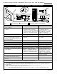
Vermont Castings Pinnacle & Stardance Direct Vent - Rear Vent Gas Heaters 5a,b 2 1a 1e 6 3 NT E EM I C 8 14 19 12b 15 16 12a 12c OFF ¥ 11a,b D LE LOCAL 9 REMOTE ON ¥ P T OFF 10a,b 13 T ILO LO PILOT ADJ 1h O H 1g 7 PI L 1c TP 4 TPTH 1f ON 1b TH 1d 17 22 21 18 20a-d 23 24 27 26 25 28 29 30 31 35 32 36 33 37 34 38 39 3457 Vermont Castings, Majestic Products reserves the right to make changes in design, materials, specifications, prices and discontinue
Vermont Castings Pinnacle & Stardance Direct Vent - Rear Vent Gas Heaters Pinnacle (PDV20) / Stardance (SDVR) Direct Vent/Rear Vent Gas Heater Models 2950, 2951, 2995, 2996, 2997, 2998 (continued) Ref. 1. 1a. 1b. 1c. 1d. 1e. 1f. 1g. 1h. 2. 3. 4. 5. 6. 7. 8. 9. 10a. 10b. 11a. 11b. 12a. Description Gas Log Assembly Log, Rear Log, Right Left Log Log, Top Log, Left - PDV20RF Log, Right - PDV Ember Strip, Left - SDV30 Ember Strip, Right - SDV30 Grille, UV30 Mesh, Grille - UV30 Cement, Gasket 3oz.
Vermont Castings Pinnacle & Stardance Direct Vent - Rear Vent Gas Heaters Pinnacle (PDV20) / Stardance (SDVR) Direct Vent/Rear Vent Gas Heater Models 2950, 2951, 2995, 2996, 2997, 2998 (continued) Ref. Description 24. Switch, ON/OFF - R/WDV Trim ON/OFF Switch - JDV 25. Control FS/HM 26. Bracket, Right Log 27. Bracket, Left Log 28. Gasket Base Pan 29. Gasket Inner Base Pan 30. Top, Stardance UV/PDV 31. Front, HM-VC 32. Door, Left - Stardance 33. Door, Right - Stardance 34. Front, Stardance OP DR 35.
Vermont Castings Pinnacle & Stardance Direct Vent - Rear Vent Gas Heaters Optional Accessories Fan Kits FK28 Fan The FK28 fan helps distribute heated air from within the firebox out into the room. The fan is controlled by a snapstat that turns power on and off as the firebox temperature rises above and falls below a preset temperature. A rheostat provides for variable fan speeds. Specifications 115 Volt / 60Hz / .
Vermont Castings Pinnacle & Stardance Direct Vent - Rear Vent Gas Heaters LIMITED LIFETIME WARRANTY PRODUCT COVERED BY THIS WARRANTY All Vermont Castings gas stoves, gas inserts, and gas fireplaces, and all Majestic or Northern Flame brand gas fireplaces equipped with an Insta-Flame Ceramic Burner, or standard steel tube burner.
Vermont Castings, Majestic Products 410 Admiral Blvd. • Mississauga, Ontario, Canada L5T 2N6 • 905-670-7777 www.majesticproducts.com • www.vermontcastings.