INSTALLER/CONSUMER SAFETY INFORMATION PLEASE READ THIS MANUAL BEFORE INSTALLING AND USING APPLIANCE WARNING! IF THE INFORMATION IN THIS MANUAL IS NOT FOLLOWED EXACTLY, A FIRE OR EXPLOSION MAY RESULT CAUSING PROPERTY DAMAGE, PERSONAL INJURY OR LOSS OF LIFE. Direct Vent Models: 33XDV, 36XDV, 39XDV FOR YOUR SAFETY Installation and service must be performed by a qualified installer, service agency or the gas supplier. WHAT TO DO IF YOU SMELL GAS: • Do not try to light any appliance.
XDV Direct Vent Gas Fireplace Table of Contents PLEASE READ THE INSTALLATION & OPERATING INSTRUCTIONS BEFORE USING APPLIANCE. Thank you and congratulations on your purchase of a CFM Corporation fireplace. IMPORTANT: Read all instructions and warnings carefully before starting installation. Failure to follow these instructions fully may result in a possible fire hazard and will void the warranty. Installation & Operating Instructions Important Curing/Burning Instructions .....................................
XDV Direct Vent Gas Fireplace Installation & Operating Instructions This gas appliance should be installed by a qualified installer in accordance with local building codes and with current CSA-B149.1 Installation codes for Gas Burning Appliances and Equipment. For USA Installations follow local codes and/or the current National Fuel Gas Code. ANSI Z223.1/NFPA 54.
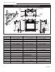
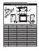
XDV Direct Vent Gas Fireplace XDV Fireplace Dimensions - Installed as Rear Vent Rough Opening Depth S 4" Dia. (102mm) 7" Dia. (178mm) E X F Recessed Nailing Flange S 5/ 8" (1 6 U m m ) V - Rough Opening Width 5/8" (16mm) Rough Opening Height T G Electrical Access Low Voltage Electrical Access W B B C Gas Line Access D Low Voltage Electrical Access Gas Line Access H M M O I A P N J K L Fig. 2 Fireplace specifications and framing dimensions. Ref.
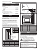
XDV Direct Vent Gas Fireplace XDV Fireplace Dimensions - Installed as Top Vent Rough Opening Depth E 7" Dia. (178mm) 4" Dia. (102mm) R S X Recessed Nailing Flange F S (1 6 5/8" (16mm) Rough Opening Height 5/ 8" U m m ) V - Rough Opening Width T Electrical Access Low Voltage Electrical Access Q B W B Gas Line Access C D Low Voltage Electrical Access Gas Line Access N O P J K A M M L Fig. 3 Fireplace specifications and framing dimensions. Ref.
XDV Direct Vent Gas Fireplace Clearance to Combustibles Top of Unit to Ceiling ................................36” (914 mm) Front of Unit to Combustibles ...................36” (914 mm) Appliance Top of Standoff .........................................0” (0 mm) Bottom ......................................................0” (0 mm) Side ..........................................................0” (0 mm) Back .........................................................
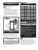
XDV Direct Vent Gas Fireplace Framing and Finishing Gas Specifications Check fireplace to make sure it is levelled and properly positioned. To mount the appliance: 1. Choose the location. 2. This unit comes with four (4) flanges pre-mounted on both sides of the fireplace to allow two different drywall thicknesses to be used. Flange “A” is for 1/2” drywall while flange “B” is for 5/8” drywall. 3. Bend the desired flanges out 90° on both sides of the fireplace.
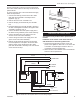
XDV Direct Vent Gas Fireplace The gas line connection can be made with properly tinned 3/8” copper tubing, 3/8” rigid pipe or an approved flex connector. Since some municipalities have additional local codes, it is always best to consult your local authority and the National Fuel Gas Code, ANSI Z223.1/NFPA 54 in the USA or the CSA-B149.1 installation code. 2. Attach the wire to the ON/OFF switch and install switch into receptacle box. Attach cover plate to switch. 3. Connect wiring to gas valve. (Fig.
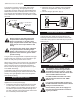
XDV Direct Vent Gas Fireplace The EB-1 Electrical junction box has been fitted standard on this model to allow for the easy connection of an optional fan kit. To connect the EB-1 box to the house electrical supply follow the steps below. 1. Unscrew the retaining screw from the EB-1 base plate and remove the EB-1 assembly from the appliance. (Fig. 9) 2. Remove the front cover of the EB-1 box. 3. Remove the plug socket assembly from the EB-1 box. 4.
XDV Direct Vent Gas Fireplace 3. Connect the white wire from the wall switch or wall thermostat to the white wire terminal from the electronic module. Connect the black wire from the wall switch or the red wire from the wall thermostat, to the red wire terminal from the electronic module. Remove Insulation 7” Diameter Notch Out Remove Screws (4) Optional Top Vent Application The 33/36/39XDV fireplaces are shipped as rear vent units.
XDV Direct Vent Gas Fireplace Top Vent Application Restrictor Plate Rear Log Bracket When the 33XDV or 36XDV models are installed as top vent fireplaces with a minimum 12” (305 mm) rise, the restrictor plate must be installed to give better flame appearance. This restrictor plate is shipped with the 33/36XDV and is located below the access control panel. 33XDV Restrictor Plate Installation 1. Remove rear log bracket located behind the burner panel. 2.
XDV Direct Vent Gas Fireplace General Venting Information - Termination Location INSIDE CORNER DETAIL V D H A V N N E L V B V F C B Fixed Closed Ope rab le V V VENT TERMINATION B V B CFM145a G Operable B V Fixed Closed V J G X B I A X AIR SUPPLY INLET M C = Clearance to permanently closed window D = Vertical clearance to ventilated soffit located above the terminal within a horizontal distance of 2’ (610mm) from the center line of the terminal E = Clearance to unventilated
XDV Direct Vent Gas Fireplace Termination Clearances Termination clearances for buildings with combustible and noncombustible exteriors. Inside Corner Alcove Applications* Outside Corner G= Combustible 6" (152 mm) G F= Combustible 6" (152 mm) Noncombustible 2" (51 mm) V Noncombustible 2" (51 mm) V C V E O F Balcony with perpendicular side wall Balcony with no side wall D C E = Min. 6” (152 mm) for non-vinyl sidewalls Min. 12” (305 mm) for vinyl sidewalls O = 8’ (2.4 m) Min.
XDV Direct Vent Gas Fireplace Twist Lock Pipes 30 When using CFM Corporation twist-lock pipe it is not necessary to use sealant on the joints. The only areas of the venting system that need to be sealed with high temperature silicone sealant are the sliding joints of any telescopic vent section used in the system.
XDV Direct Vent Gas Fireplace Vent Opening for Combustible Wall 9³⁄₈” (240mm) Rear Vent Top View 20" (508 mm) Framing Detail 10³⁄₈” (264mm) DVR584-600 Fig. 21 Rear vent application, no elbows. Fireplace Hearth 20" DVR584-600 20" (508 mm) (508 mm) Rear Max.vent no elbows Max. 2/99 djt 45° Opening for Noncombustible Wall 7¹⁄₂” (190 mm) 45° VO584-100 Fig. 23 Locate vent opening on wall. Max. Length 12” (305mm) Adjustable Zero Clearance Sleeve #8 Screws (2) REAR VENT-TOP VIEW FP836 Fig.
XDV Direct Vent Gas Fireplace Finished Wall Rise Vent Termination FP1472 Fig. 27 There must be a 1/2” rise per foot length. Vertical Sidewall Applications FP1005 Fig. 25 Side view of final unit location. Rear WallFP1005 Vent Installations Side View Vent Termination Flex Vent Pipe 1/25/00 djt Follow Steps 1 and 2 on Page 15. Step 3 Install the 4” (102 mm) flex vent pipe to the appliance collars described in “General Information Assembling Vent Pipes”, Page 11.
XDV Direct Vent Gas Fireplace • The maximum number of 90° elbows per side wall • B 7’ (178 cm) installation is three (3). (Fig. 28) If a 90° elbow is fitted directly on top of the fireplace flange, the maximum horizontal vent run before the termination or a vertical rise is 36” (914 mm). (Fig. 29) 3 x 90° Elbows 3 x 90° Elbows A 10’ (254 cm) 8’ (244 cm) A + B = 17’ (518 cm) Max. V584-201 Fig. 31 Maximum vent run with elbows. FP1176 Fig. 28 Maximum three (3) 90° elbows per installation.
XDV Direct Vent Gas Fireplace Vertical Sidewall Installation Twist Lock Pipe Max. Length 12” (305mm) Adjustable Zero Clearance Sleeve STEP 1 #8 Screws (2) Locate vent opening on the wall. It may be necessary to first position the fireplace and measure to obtain hole location. Depending on whether the wall is combustible or noncombustible, cut opening to size. (Fig. 33) (For combustible walls first frame in opening.
XDV Direct Vent Gas Fireplace spring. Place the next spring 6” (152 mm) from the last spring. Finally, place the last spring 12” (305 mm) from the last spring installed. (Fig. 37) X X 4” Flex Vent Pipe 12" (305mm) Spacer Spring 6" (152mm) 5" (127mm) 6���" (172mm) FP1474 Fig. 37 Install spacer springs. FP1182 Fig. 36 Horizontal length requirement. STEP 7 Apply high temperature sealant to 4” (102 mm) and 7” (178 mm) collars or the termination one inch away from the end.
XDV Direct Vent Gas Fireplace Do not backfill around snorkel. Below Grade Installations When it is not possible to meet the required vent terminal clearances of 12” (305 mm) above grade level a snorkel kit is recommended. This allows installation depth of down to 7” (178 mm) below grade level. The 7” is measured from the center of the horizontal vent pipe as it penetrates through the wall. Ensure the sidewall venting clearances are observed.
XDV Direct Vent Gas Fireplace Vertical Through-the-Roof Installation Max. Height 40’ (12.2m) Min. Height 8’ (2.4m) Max. 10’ (3m) Support Straps Every 3’ (.9m) Max. Height 40’ (12.2m) Min. Height 8’ (2.4m) Max. 10’ (3m) FP1183 Fig. 41 Support straps for horizontal runs. 1 + 2 + 3 + 4 = 270° 1 2 3 4 1. Locate your fireplace. 2. Plumb to center of the (4”) flue collar from ceiling above and mark position. 3. Cut opening equal to 9³⁄₈” x 9³⁄₈” (240 x 240 mm). 4.
XDV Direct Vent Gas Fireplace 3 #5 Sheet Metal Screws per Joint Sealant Storm Collar Typical Roof Support Application Typical Ceiling Support Application FP1184 Typical roof/ceiling Min. support apps. 2' (610 mm) TWL101a FP1184 Fig. 44 Venting supports. Fig. 46 Roof flashing. TWL101a Twist Lock Pipe 2/8/99 djt FP1185 Fig. 45 Minimum termination to roof clearance.
XDV Direct Vent Gas Fireplace Venting Components 7TDVRVT - Through the wall Rear Vent Termination 584A venting components rear vent term 4/6/99 djt 584B Vent components Starter Kit 2/25/99 djt Starter Kit Model 7TDVSK - Sidewall Venting (Twist Lock Pipe) Model 7FDVSK - Sidewall Venting (Flex Vent Pipe) Models 7TDVTK/TV - Hot Touch Termination Kits Model 7TDVTVTK/TV - Cool Touch Termination Kit Starter Kit - Model 7TDVSKV - Vertical Venting for 7TDVSKV-A order 1/12 to 6/12 roof pitch for 7TDVSKV-B order
XDV Direct Vent Gas Fireplace Operating Instructions Glass Information Window Frame Assembly Only glass approved by CFM Corporation should be used on this fireplace. Fireplace Front • The use of any non-approved replacement glass will void all product warranties. • Care must be taken to avoid breakage of the glass. • Do not operate appliance with glass front Clamps Glass Panel removed, cracked or broken.
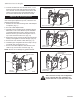
XDV Direct Vent Gas Fireplace Installation of Logs Log Identification Chart The logs are fragile and should be handled with care. Keep the packaging material out of the reach of children and dispose of the mterial in a safe manner.
XDV Direct Vent Gas Fireplace 4. Place the log front (A50). Place the two underside holes of the log over the two pin studs of the bracket located at the front of the burner housing. (Fig. 52) 5. Place the log top right (A52). Place the bottom round hole onto the knob at the right side of the rear log. The cross section of the log will rest on top of the center right log. (Fig. 53) 6.
XDV Direct Vent Gas Fireplace Log Center Right (B153) Figure 55 2. Place the log, center right (B153). Place the two underside holes of the log over the two pin studs of the bracket support center log on the right. (Fig. 55) Figure 56 LG949 3. Place the log, front (B155). Place the two underside holes of the log over the two pin studs of the bracket front log support located at the front of the burner housing.����� (Fig.
XDV Direct Vent Gas Fireplace 39XDV NOTE: Refer to Figure 57 for bracket and bend locations. 1. Place the log front right. Hold the log with the pointed end toward the left. Place on top of burner toward the right. Slide the log toward the front until it comes in contact with the bracket at the front of the burner housing behind the burner tube. (Fig. 59) Adjust the log until the pointed end on the left is aligned with the left edge of the bracket. (Fig.
XDV Direct Vent Gas Fireplace 3. Place log rear. The rear log sits in the firebox at an angle toward the left over the rear log bracket and the left side of the burner. (Fig. 59) Set the log on the rear log bracket. Slide the log to the right until the bracket lines up with the left side of the notch on the rear log. Swing the left end of the log toward the front until it makes contact with the stop bracket. (Fig. 62) Log Rear Figure 62 LG467 Figure 63 4.
XDV Direct Vent Gas Fireplace Burner Lava Rock Placement Flame Characteristics Place the contents of the small bag of ceramic burner lava embers on the burner in front of the front logs. Do not place burner lava rock in the inside corners of the front logs. It is important to periodically perform a visual check of the pilot and the burner flames. Compare them to Figures 68-69. If any of the flames appear abnormal call a service person.
XDV Direct Vent Gas Fireplace Yellow Flames 33XDV LG959 Yellow Flames Red Glow ����� ���������������� 36XDV ���� LG953 39XDV Yellow Flames Red Glow ������ ���������������� ���� LG470 Red Glow Fig. 69 Correct burner flame appearance.
XDV Direct Vent Gas Fireplace Lighting and Operating Instructions FOR YOUR SAFETY READ BEFORE LIGHTING WARNING:If you do not follow these instructions exactly, a fire or explosion may result causing property damage, personal injury or loss of life. A. This heater has a pilot which must be lit manually. When lighting the pilot follow these instructions exactly. B. BEFORE LIGHTING smell all around the heater area for gas.
XDV Direct Vent Gas Fireplace Lighting & Operating Instructions For Fireplaces equipped with SIT822 Gas Valve (EN or EP) Warning: If you do not follow these instructions exactly, a fire or explosion may result, causing property damage, personal injury and loss of life. For Your Safety, Read the Following Warnings before Lighting the Appliance A. This fireplace is equipped with an ignition device which automatically lights the pilot. DO NOT try to light the pilot by hand. B.
XDV Direct Vent Gas Fireplace Instructions for RF Comfort Control Valve The Comfort Control Valve allows remote control of temperature, fan and flame appearance. NOTE: The antenna should hang in free air away from grounded metal. Operation 1. If the manual switch is in remote position, switch it to LOCAL. (Fig. 70) 2. Turn the pilotstat knob counterclockwise from OFF to the PILOT position, push the knob down, and hold in position. The pilot valve opens and allows gas to flow to the pilot burner. 3.
XDV Direct Vent Gas Fireplace Delay Timer Mode Pilot Assembly The shut off delay timer has a maximum of 2 hours and a minimum of zero minutes. To change the timer level, press the time key followed by an arrow key. Pushing the key once will change the timer by 10 minutes. Fan Auto Mode In the AUTO mode, the room temperature, set temperature, flame and fan levels will be shown. AUTO will appear next to both the flame and fan icons.
XDV Direct Vent Gas Fireplace 2. Slide the Remote/Local switch to REMOTE and teach the valve a transmitter (refer to Item 6, page 32). The Error Code will clear itself after approximately 1¹⁄₂ minutes and return to normal operation. LED Count Service Action Auto Path If the manual switch is set to REMOTE, press the mode button to display AUTO on the transmitter.
XDV Direct Vent Gas Fireplace Comfort Valve system control sequence of operation with transmitter Set manual switch to local or remote Five minute wait period Light pilot burner Did the LED stop blinking? Yes Review LED failure analysis Release pilotstat knob Yes Turn pilotstat knob from PILOT to ON Move switch from local to remote. Press any key on transmitter.
XDV Direct Vent Gas Fireplace Troubleshooting the Gas Control System SIT NOVA 820 MILLIVOLT VALVE NOTE: Before troubleshooting the gas control system, be sure external gas shut off is in the “On” position. WARNING: REMOVE GLASS FRONT BEFORE DOING ANY GAS CONTROL SERVICE WORK. SYMPTOM 1. Spark ignitor will not light POSSIBLE CAUSES A. Defective or misaligned electrode at pilot. B. Defective ignitor (Push Button) 2. Pilot will not stay lit after A.
XDV Direct Vent Gas Fireplace Troubleshooting the Gas Control System SIT 822 Valve with Synetek Electronic Control Operating Diagram Normal Operation Abnormal Operation ON/OFF Switch Closed? 5 sec Inter-Trial Delay YES Safe Start Check On? NO YES 0 Sec Purge Ignition Trial: 30 sec Spark ON Pilot Valve ON.
XDV Direct Vent Gas Fireplace Conversions must be completed by qualified personnel 2. Insure the rubber gasket (D) is properly positioned Fuel Conversion Instructions To convert the XDV units for use with a different gas follow these instructions. Before proceeding, turn control knob on valve to “OFF” and turn gas supply OFF. Turn OFF any electricity that may be going to the appliance. CAUTION: Logs may be HOT! Allow to cool before proceeding. 1. Open louvre assembly bottom to gain access to valve.
XDV Direct Vent Gas Fireplace Shutter Retaining Screw Air Shutter Burner Pan Front View CO103 Fig. 77 RemoveCO103 air shutter from burner pan. Gas Conversion Air shutter fully open. LP: Rear air shutter 2/15/99 djt Front air shutter fully open. 7. Reinstall burner housing assembly and front burner tube. 4. Converting LP to NG, remove bracket/gasket assembly by unfastening the screw which secures the bracket to the burner tray base. Discard bracket and refasten the screw into the hole. (Fig.
XDV Direct Vent Gas Fireplace Installation Precautions Before proceeding, turn control knob on valve to OFF and turn gas supply OFF. Turn OFF any electricity that may be going to the appliance. CAUTION: Logs may be hot! Conversion Procedure 1. Open bottom grille to gain access to valve. Remove glass door. (Refer to “Window Frame Assembly Removal Section” Page 24, Fig. 48) 2. Remove logs if previously installed. CAUTION: Logs may be hot! 3.
XDV Direct Vent Gas Fireplace Shutter Retaining Screw 6. Replace the burner housing with the new one provided in kit. 7. Reassemble the burner housing assembly, the burner tube assembly and the fettle in reverse order. Burner Pan Pilot Orifice Conversion Air Shutter Front View CO103 Fig. 86 Remove air shutter from burner pan. CO103 Gas 5. Install conversionConversion air shutters on burner pan. ReAir shutter place air shutter retaining screw. Adjust both air shut2/15/99 djt ters.
XDV Direct Vent Gas Fireplace Table 1 Injector Orifice Size Matrix 44 Kit # 20011506 Model 39XDVRP Kit # 20011505 20011504 Model 39XDVRN 39XDVEN Conversion to Natural Gas Burner Orifice Front Part # Rear Part # #53 20007347 #44 30000334 (.059”) (.086”) Conversion to LP Burner Orifice Front Part # Rear Part # #64 20010935 #54 20000130 (.036”) (.
XDV Direct Vent Gas Fireplace Maintenance Burner and Burner Compartment It is important to keep the burner and the burner compartment clean. At least once per year the logs and lava rock/ember material should be removed and the burner compartment vacuumed and wiped out. Remove and replace the logs as per the instructions in this manual. Always handle the logs with care as they are fragile and may also be hot if the fireplace has been in use. FK24/FK12 Fan Assembly The fan unit requires periodic cleaning.
XDV Direct Vent Gas Fireplace 1 33XDV 1 36XDV 1 39XDV 1a 1a 1i 1c 1c 1d 1b 3 4 1b 1e 1f 2 1a 1j 1g 1f 1e 1h 1c 1d 10 5 9 9a,b 6 7 14 19 11 8 12 13 16 6a,b 15 21a,b 25 27 22a,b 29 61 40 35 17-18a,b 23a,b 34a,b 38 30 T OFF • 50 36 28 D 51 LE REMOTE LOCAL 32 26 24 ON • PILO 37 33a,b 31 41 39 53 45 46 52 47 48 54 LO 56 HI 49 55 58 57a,b 69 59 63 60 62 66 64 67 71 61 65 70 68 CFM Corporation reserves the right to make chan
XDV Direct Vent Gas Fireplace 33XDV/36XDV/39XDV (continued) Ref. Description 1. 1a. 1b. 1c. 1d. 1e. 1f. 1g. 1h. 1i. 1j. 2. 3. 4. 5. 6. 6a. 6b. 7. 8. 9. 9a. 9b. 10. 11. 12. 13. 14. 15. 16. 17a. 17b. 18a. 18b. 19. 20. 21a. 21b. 22a. 22b. 23a. 23b. 24. 25. 26. 27. 28. 29. 30. 31. 32. 33a.
XDV Direct Vent Gas Fireplace 33XDV/36XDV/39XDV (continued) Ref. Description 33b. 34a. 34b. 35. 36. 37. 38. 39. 40. 41. 42. 43. 44. 45. 46. 47. 48. 49. 50. 51. 52. 53. 54. 55. 56. 57a. 57b. 58. 59. 60. 61. 62. 63. 64. 65. 66. 67. 68. 69. 70. 71. Orifice Pilot LP RF Pilot Assembly Nat. RF Pilot Assembly LP RF Thermopile (RF) Pilot Tubing w/Fittings PSE Ignitor Piezo Honeywell Valve SIT 820.
XDV Direct Vent Gas Fireplace Optional Accessories Available Fan Kits FK12 Fan Assembly 1. Open louvre assembly bottom. 2. Install FK12 fan in back of unit between hearth supports. (Fig. 90) 3. Secure fan on velcro strips. 4. Power to the fan can be supplied by plugging the supply lead into a conveniently located wall socket or by using a hard-wired EB-1 connector box. 5. Be sure fan motor does not touch hearth supports.
XDV Direct Vent Gas Fireplace Remote Controls Optional remote control units are available to control different functions of the appliance.
XDV Direct Vent Gas Fireplace Optional Trim Kits Louvre Accent Trim Appliance Model Main Louvre Kit Additional Louvre Polished Brass 33XDV 33DVLMP 33DVLAP 36XDV 36DVLMP 36DVLAP 39XDV 39DVLMP 39DVLAP Antique Brass 33XDV 33DVLMA 33DVLAA 36XDV 36DVLMA 36DVLAA 39XDV 39DVLMA 39DVLAA Rustic Bronze 33XDV 33DVLMR 33DVLAR 36XDV 36DVLMR 36DVLAR 39XDV 39DVLMR 39DVLAR Pewter 33XDV 33DVLMS 33DVLAS 36XDV 36DVLMS 36DVLAS 39XDV 39DVLMS 39DVLAS Regular Trim Kit Appliance Model Trim Kit 33XDV 33DVRTKP 33XDV 33DVRTKA 33XDV 3
XDV Direct Vent Gas Fireplace 52 10009383
XDV Direct Vent Gas Fireplace 10009383 53
XDV Direct Vent Gas Fireplace 54 10009383
LIMITED LIFETIME WARRANTY XDV Direct Vent Gas Fireplace PRODUCT COVERED BY THIS WARRANTY All Vermont Castings gas stoves, gas inserts, and gas fireplaces, and all Majestic brand gas fireplaces equipped with an Insta-Flame Ceramic Burner, or standard steel tube burner.
Efficiency Ratings Model 33XDVRN 33XDVRP 33XDVEN 33XDVEP 36XDVRN 36XDVRP 36XDVRFN 36XDVRFP 36XDVEN 36XDVEP 39XDVRN 39XDVRP 39XDVEN 39XDVEP EnerGuide Ratings Fireplace Efficiency (%) 60.1 60.1 66.2 66.2 61.8 61.8 61.8 61.8 66.6 66.6 61.6 61.6 65.8 65.8 Steady State (%) Fan-OFF Fan-ON 80 81 81 82 80 81 81 82 83 84 84 85 83 84 84 85 83 84 84 85 80 81 81 82 80 81 81 82 CFM Corporation 2695 Meadowvale Blvd. • Mississauga, Ontario, Canada L5N 8A3 800-668-5323 • www.cfmcorp.com D.O.E.