
- Vermont Castings Direct Vent Homeowner's Manual 33XDV, 36XDV, 39XDV

10009383 7
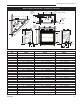
XDV Direct Vent Gas Fireplace
Max. Min.
Input Input
Model Fuel Gas Control BTU/h BTU/h
33XDVRN Nat. Millivolt Hi/Lo 21,500 4,400
33XDVRP Prop. Millivolt Hi/Lo 21,500 5,425
33XDVEN Nat. 24 Volt Hi/Lo 21,500 4,400
33XDVEP Prop. 24 Volt Hi/Lo 21,500 5,425
36XDVRN Nat. Millivolt Hi/Lo 27,500 5,150
36XDVRP Prop. Millivolt Hi/Lo 27,500 5,500
36XDVRFN Nat. Comfort Contrl 27,500 5,810
36XDVRFP Prop. Comfort Contrl 27,500 6,225
36XDVEN Nat. 24 Volt Hi/Lo 27,500 5,150
36XDVEP Prop. 24 Volt Hi/Lo 27,500 5,500
39XDVRN Nat. Millivolt Hi/Lo 30,000 6,700
39XDVRP Prop. Millivolt Hi/Lo 30,000 5,800
39XDVEN Nat 24 Volt Hi/Lo 30,000 6,700
39XDVEP Prop 24 Volt Hi/Lo 30,000 5,800
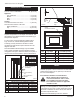
Framing and Finishing
Check fireplace to make sure it is levelled
and properly positioned.
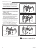
To mount the appliance:
1. Choose the location.
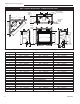
2. This unit comes with four (4) flanges pre-mounted
on both sides of the fireplace to allow two different
drywall thicknesses to be used. Flange “A” is for
1/2” drywall while flange “B” is for 5/8” drywall.
3. Bend the desired flanges out 90° on both sides of
the fireplace. Slide the fireplace into the framed
opening until the flanges contact the front surfaces
of the framing. Level the unit and secure it firmly in
place.
Fig. 5 Nailing flanges.
Flange Drywall
Position Depth
A 1/2” / 13 mm
B 5/8” / 16 mm
Flange Location for
Desired Drywall Depth
FP1539
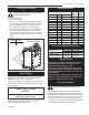
Noncombustible materials such as brick or tile may be
extended over the edges of the face of the fireplace.
DO NOT cover any vent or grille panels.
If a Trim Kit is going to be installed on the fireplace, the
brick or tile will have to be installed flush with the edges
of the fireplace.
Final Finishing
33XDV / 36XDV / 39XDV
Certified To
ANSI Z21.88-2005 / CSA 2.33-2005
Vented Gas Fireplace Heaters
Gas Specifications
Inlet Minimum 5.5” w.c. 11.0” w.c.
Inlet Maximum 14.0” w.c. 14.0” w.c.
Manifold Pressure 3.5” w.c. 10.0” w.c.
Gas Inlet and Manifold Pressures
Natural LP (Propane)
High Elevations
Input ratings are shown in BTU per hour and are
certified without deration for elevations up to
4,500 feet (1,370m) above sea level.
For elevations above 4,500 feet (1,370m) in USA,
installations must be in accordance with the cur-
rent ANSI Z223.1/NFPA 54 and/or local codes hav-
ing jurisdiction.
In Canada, please consult provincial and/or local
authorities having jurisdiction for installations at
elevations above 4,500 feet (1,370m).
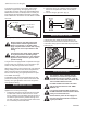
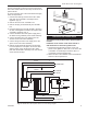
Gas Line Installation
When purging the gas lines, the front win-
dow frame assembly must be removed.
The gas pipeline can be brought in through the rear
of the appliance as well as the bottom. Knockouts are
provided on the bottom behind the valve to allow for the
gas pipe installation and testing of any gas connection.
It is most convenient to bring the gas line in from the
rear right side of the valve as this allows fan installation
or removal without disconnecting the gas line.
A
B
FP1539a
flanges w/standoffs
5/05
Units: GFDN3L1, GFDE3L1, GFDN3J1, GFDI3J1,
GFDE3JI, GFDN3K1, GFDE3K1