BFC Balance Flue (Closed Combustion) Heat-Circulating Fireplace Model: BFC36 Homeowner’s Installation and Operating Manual 647 BFC cover 8/18/00 djt For use in the U.S. / Canada Underwriter’s Laboratories Report No. MH6018 CFM Specialty Home Products 410 Admiral Blvd. • Mississauga, Ontario, Canada L5T 2N6 • 905-670-7777 www.majesticproducts.com • www.vermontcastings.com DO NOT DISCARD THIS MANUAL: Retain for future use. 7412647 8/05 Rev.
BFC36 Balance Flue Heat-Circulating Fireplace Safety Information Please Read This Manual Before Installing and Using Fireplace IMPORTANT: Read all instructions and warnings carefully before starting installation. Failure to follow these instructions may result in a possible fire hazard and will void the warranty. Burn only solid wood fuel or gas logs. Description The BFC36 is intended for operation only with the doors closed. The BFC36 fireplace is a solid fuel, woodburning fireplace.
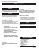
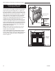
BFC36 Balance Flue Heat-Circulating Fireplace BFC36 Balanced Flue Heat-Circulating Fireplace ������" (624mm) Rough ����" Opening (197mm) Depth 51����" (1297mm) ���" (13mm) Rough Opening Width 43" (1092mm) �����" (179mm) �� ���" Rough Opening Height ��� �" ( �� ��� "( 51����" (1297mm) 91 � 18 ��" ( 34 16 m mm m ) ) 8m m ) ��" (610mm) 23" (584mm) 13���" Dia. (343mm) 11" Dia. (179mm) 8" Dia.
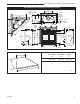
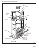
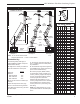
BFC36 Balance Flue Heat-Circulating Fireplace Termination Cap Storm Collar Pan Flashing Batt Insulation (Cut out around firestop) Draftstop Firestop Ceiling Level Standoff Trim Ledge Standoff Surround Glass Door Gas Line Access Hole (Each Side) Romex Pigtail Gas Line Access Knockout (Each Side) Air Inlet Basket Grate Bottom Grille Top Grille and Air Outlet Metal Safety Strip(s) Shown not inplace (1,2 or 3 pieces) Nailing Flange FP554c Fig. 2 Fireplace and chase parts identification.
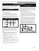
BFC36 Balance Flue Heat-Circulating Fireplace Chimney Requirements - Offset Installations OFFSET CHIMNEY FLUE EXIT RISE Chimney Section A D E 6 FT. C G 30° Offset Elbow Rise Offset H 30° Return Elbow 30° Offset Elbow B 30˚ Elbow Offsets G TCS8A Support H Hearth Floor Example 1 Example 2 Notes: G + H cannot exceed 20 feet. Air Space Clearances: = 2” Min.
BFC36 Balance Flue Heat-Circulating Fireplace Planning Information Preplanning an installation is very important to ensure safety and to save time and money. An installer must predetermine where a fireplace will be set and how the chimney system will be run. Mounting the Fireplace A fireplace may only be mounted on the following surfaces: 1. A flat combustible surface. 2. A raised wooden platform. 3. A concrete block or other solid object placed beneath each of the four (4) corners of the fireplace.
BFC36 Balance Flue Heat-Circulating Fireplace Chimney Supports The chimney system is supported by the fireplace for vertical chimney heights less than 30’ (9m) above the hearth. Chimney supports are required if the vertical height exceeds 30’ (9m). Locate chimney supports at ceiling holes or other structural framing at 30’ (9m) heights. Spacing between chimney supports must not exceed 30’ (9m). Use Chimney Support Model TCS8A. (NOTE: The TCS8A cannot be mounted directly to the fireplace.
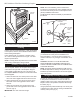
BFC36 Balance Flue Heat-Circulating Fireplace Hard Flat Surface NOTE: Check local building codes to determine if junction box is required at the romex pigtail/house wire connection Also check junction box and speed control (SCVS) installation instructions. The Model FKSX-A blower assembly is preinstalled in the BFC36. Fireplace Electrical Coverplate Romex Pigtail (Provided) Wire Nuts (Not provided) Insulation Black Platform Ground White FPC555a FP1062 Fig. 7 Insulating between platform and fireplace.
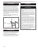
BFC36 Balance Flue Heat-Circulating Fireplace Ceiling Chimney Hole/ Possible Obstructions Chimney Centerline Actual Centerpoint The size of the hole in ceiling will vary with the angle at which the chimney passes through ceiling. Drive a nail up through ceiling at marked chimney center point. Go to floor above and see where hole will be cut. Check to see where existing ceiling joists and other possible obstructions are located...i.e. wiring, plumbing etc...
BFC36 Balance Flue Heat-Circulating Fireplace Positioning, Safety Strips, Securing the Fireplace Slide fireplace into position. Lift the fireplace front slightly and slide the metal safety strips under front bottom edge about 1¹⁄₂” (38mm), allowing the remainder to extend in front of firebox. Overlap strips at least 1/2” (13mm) to provide a positive joint. (Flat safety strips are packed with fireplace.) (Fig. 12) Metal Safety Strips (1,2 or 3 pcs.
BFC36 Balance Flue Heat-Circulating Fireplace Installing the Chimney System Pipe Section Start by attaching the first chimney section to the collar on top of the fireplace. UP Install the pipe as pictured in Figure 14. When you get a good lock, you will hear the pipe clearly snap together. Once sections are snap-locked in place, it is extremely difficult to get them apart. Make sure the pipe is firmly snapped and locked together as each pipe section is mounted.
BFC36 Balance Flue Heat-Circulating Fireplace Firestop spacers are not available for, nor are they required on vertical walls. DO NOT put any sealant around the area where the outer pipe slides through the firestop spacer. If you seal this area, it may cause a fire hazard. If you encounter additional ceilings, repeat same steps required for first ceiling installation. See firestop illustration in Page 11, Figure 16.
BFC36 Balance Flue Heat-Circulating Fireplace Installing Top Housing or Termination Air Space Clearances Follow the installation instructions provided with the CFM Corporation chimney termination you have selected. Combustible framing material MUST NOT penetrate AIR SPACE (shaded areas). Installing Chimney in a Chase Refer to Page 4, Figure 2 for an illustration of a typical chase installation. CAUTION: Treatment of firestop spacers and construction of chase may vary with type of building.
BFC36 Balance Flue Heat-Circulating Fireplace Combustible Mantel Shelf and Trim 12" (305mm) Max. Finished Wall 1¹⁄₂" (38mm) Stud 12" (305mm) Min. Standoff 6" (159mm) Min. Noncombustible Material Circulating Front Fireplace Opening Side View ¹⁄₂" 2 x 4 Stud Finished Wall Fireplace Front Must be sealed with noncombustible material FP531b Fig. 19 Mantel clearance. FP531b mantel clearances 9/03 djt Face Plate * 1¹⁄₂" Ref. * 12” from top of grille opening. ** 6” from top of grille opening.
BFC36 Balance Flue Heat-Circulating Fireplace Side Wall Protection Hearth Installation Adjacent combustible side walls that are within minimum dimensions shown in Figure 24 of the fireplace opening must be protected with CFM Corporation Wall Shield Model SP40 or a specifically built wall shield described in Figure 18. A hearth extension is required to protect a combustible floor in front of the fireplace. Refer to Figure 21 for minimum dimensions and mounting detail.
BFC36 Balance Flue Heat-Circulating Fireplace WARNING: Hearth extension must be installed in accordance with Figure 23 and must not cover the bottom front opening of the circulating model. Alternate noncombustible materials may be used providing the (total) thermal resistance (Rt value) of the alternate material employed is greater than or equal to R = 1.09 Thermal resistance (R) or thermal conductivity (K), may be obtained from manufacturer of the material. Factors are related by the formula K = 1/R. (Fig.
BFC36 Balance Flue Heat-Circulating Fireplace BTU input of a gas appliance installed in fireplace should be rated less than 100,000 BTU/Hr. Glass Door Operation The BFC36 is intended for use only with the doors fully closed. (Fig. 25) Gas pipe installation is intended for connection to a decorative gas appliance only when (1.) incorporating an automatic shutoff device and (2.) complying with the Standard for Decorative Gas Appliances for Installation in Vented Fireplaces (ANSI Z21.
BFC36 Balance Flue Heat-Circulating Fireplace 3 1 24 2 6 25, 26 21, 22, 23 27 20 27 8 10 9 � 14 5 15 7 12 11 13 18 16 17 19 CFM Specialty Home Products reserves the right to make changes in design, materials, specifications, prices and discontinue colors and products at any time, without notice. BFC Balanced Flue Fireplace Ref. 1. 2. 3. 4. 5. 6. 7. 8. 9. 10. 11. 12. 13. 14. 15. 16. 17. 18. 19. 20. 21. 22. 23. 24.
BFC36 Balance Flue Heat-Circulating Fireplace BFC Balanced Flue Fireplace Ref. 25. 26. 27.
BFC36 Balance Flue Heat-Circulating Fireplace Accessories The following accessories for this appliance are available from your local Vermont Castings, Majestic Products distributor. Should you need additional information beyond what your distributor can furnish, contact: CFM Specialty Home Products, 410 Admiral Blvd., Mississauga, Ontario, Canada L5T 2N6, Attn: Technical Services.
BFC36 Balance Flue Heat-Circulating Fireplace Chimney Components Component Description Model Number Chimney Support Used to support chimney for each of 30’ vertical height and 6’ of angled chimney run Required at each floor level and attic on multi-story installation Required in Canada Top housing of simulated brick pattern available in red, tan or white. Appropriate adapter is required (8CA). Flashing included.
BFC36 Balance Flue Heat-Circulating Fireplace 22 7412647
BFC36 Balance Flue Heat-Circulating Fireplace LIMITED WARRANTY & 30 YEAR PROTECTION PLAN For Vermont Castings, Majestic Products PRE-ENGINEERED Fireplace Systems CFM Specialty Home Products warrants its Pre-Engineered Fireplace (“Fireplace”) and the CFM Specialty Home Products-supplied firegrate, glass doors, outside air system, fan motor, and liners to be free from defects in material or workmanship, as follows: A.
CFM Specialty Home Products 410 Admiral Blvd. • Mississauga, Ontario, Canada L5T 2N6 • 905-670-7777 www.majesticproducts.com • www.vermontcastings.