User’s Manual Under Cabinet Series VEHOOD3610 NOTE: PLEASE INSPECT HOOD IMMEDIATELY UPON RECEIVING. CLAIM OF DAMAGE AFTER 7 DAYS OF DELIVERY WILL BE DENIED. This unit is designed for indoor residential use only. DO NOT USE OVER A WOOD GRILL OR MOUNT IN OUTDOOR ENVIRONMENT. Please read this manual thoroughly before installing your range hood. Store it in a safe location for when you need to reference it in the future.
TABLE OF CONTENTS 1 SAFETY INFORMATION ........................................................................ 2-3 CONTENT CHECKLIST ............................................................................. 4 MEASUREMENTS .................................................................................. 5 PREPARATION ............................................................................... 6 – 7 INSTALLATION ................................................................................
2 SAFETY INFORMATION SAFETY INFORMATION TO REDUCE THE RISK OF A FIRE, ELECTRICAL SHOCK, AND/OR INJURY OBSERVE THE FOLLOWING: Unit is intended for indoor residential use only. If you should have questions, contact the manufacturer at the address or telephone number listed in the warranty. In case the unit should need to be cleaned or repaired, switch power off at service panel and lock service disconnecting means to prevent power from being switched on accidentally.
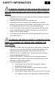
SAFETY INFORMATION 3 TO REDUCE THE RISK OF FIRE, OR ELECTRIC SHOCK, DO NOT USE THIS FAN WITH ANY SOLID-STATE SPEED CONTROL DEVICE. Regardless of heat level, never leave any surface materials unattended while operating an open flame. Always turn hood ON when cooking at high heat. Depending on amount of usage, clean ventilating fans and filters frequently. Grease should not be allowed to accumulate on fan or filter. For instructions on the how to clean, see maintenance page.
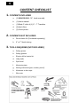
4 CONTENT CHECKLIST 1. CONTENTS INCLUDED a. (1) VEHOOD3610 - 36” hood assembly b. (1) User’s manual c. (1) Black 6” collar & (1) 6” – 7” Transition d. (3) Mesh filters e. (1) Screw packet 2. CONTENTS NOT INCLUDED a. Recirculation Kit (Purchased separately) b. 6” or 7” Metal ducting 3. TOOLS REQUIRED (NOT INCLUDED) a. Safety gloves b. Safety glasses c. Electric drill w/ starter bit d. Utility knife e. Spirit level f. Measuring tape g. Writing instrument (pen, marker, pencil) h.
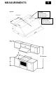
MEASUREMENTS Fig.
6 PREPARATION 1. BEFORE YOU START **DO NOT INSTALL IF DAMAGED** **RETURN OR EXCHANGE WILL BE DENIED IF INSTALLED** a. Confirm you have all parts and required tools for this installation. b. Installation may take at least 2 to 3 hours from start to finish. c. Minimize the number of duct elbows (turns) used to maximize hood performance d. Duct elbows should be no closer than 12” to each other, further apart if possible. e. At least two people are needed for installation. f.
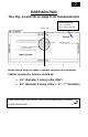
7 PREPARATION Use Fig. 1a and 1b on page 5 for measurements Center Line Electrical Opening 1 ⅞” from Rear 13 ⅜” from Centerline Install wood strips to level if cabinet bottoms are recessed. Cabinet opening for exhaust should be: 6½” diameter if using collar ONLY 8¼” diameter if using collar + 6” – 7” transition Place hood under the cabinet to be installed and mark 4 keyholes to drill starter hole.
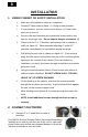
8 INSTALLATION 1. UNDER CABINET OR SOFFIT INSTALLATION a. Make sure all preparation steps are completed. b. Connect 6” black collar to hood. (1) Using screws provided c. If using transition, connect transition with damper to 6” black collar, wider part to front (2) d. Secure collar and transition with sheetmetal screws and/or duct tape for an air-tight seal. Do not impede damper movement. (3) e. Cutout hole for 6” or 7” diameter duct exhaust hole in cabinet or soffit, per figure 1C.
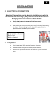
9 INSTALLATION 3. ELECTRICAL CONNECTION Electrical Connection can be done by installing an outlet in the cabinet and securing a plug onto the wires from hood or bringing wires into hood as shown below. a. Verify that power is turned off at the source. b. Make electrical connections with wire nuts (Purchased Separately) as shown. If house wiring is not 2-wire with a ground wire, a ground must be provided by the installer. Green or Bare = Ground Black = Hot White = Neutral 4. Completion a.
10 Optional Recirculation Kit * Installation Electrical Opening 1-3. 6. 4. Optional Recirculating Kit Purchased Separately from your Dealer 1. Place Recircutating Vent under cabinet and mark position of holes allowing for unit to slide back in the keyhole slots. (1) 2. Drive screws into underside of cabinet leaving a ⅛” protrusion. 3. Install metal vent to underside of cabinet onto mounting screws and slide back to rear wall. Tighten Screws. 4.
11 OPERATION & FEATURES 1. EASY ACCESS CONTROL SWITCH (from left to right) 0 Button 0 – Fan Off 1 Button 1 – Low 2 Button 2 – Medium 3 Button 3 – High Light On/Off Control 0 1 2 3 2. MESH FILTERS a. (3) 10-3/4” x 15” Dishwasher Safe Aluminum Mesh filters 3. PUTTING IN THE MESH FILTERS a. Insert the Filter into the unit at an angle. (Fig. 3b) b. Push the Mesh filter upward(Fig. 3c) c. Snap into place(Fig. 3c) Fig. 3b Fig.
12 CLEANING & MAINTENANCE WARNING!!! To prevent the possibility of a fire and explosion, do not use flammable liquids or solvents to clean the unit or any of its parts. Check to make sure all power sources are disconnected before servicing or taking unit apart for cleaning. Please thoroughly clean the unit weekly 1. RANGE HOOD a. Use household cleaner to remove grease or dirt from the outer shell of the unit.
TROUBLESHOOTING 13 TROUBLESHOOTING WARNING!!! Check to make sure all power sources are disconnected before starting any troubleshooting. Safety gloves and glasses should be worn when working on the unit. Serious injury or death may occur if safety precautions are not followed. VEHOOD3610 Series LED Light Issue 1. LED lights may need to be changed. Contact EuroChef or replacement bulb. Unit Lacks Power 1. Confirm that circuit breaker is “ON” 2. All wiring is connected. Unit making humming noise 1.
14 Parts / Replacement & Wiring Diagram PARTS LIST Item Name Part Number 1 Spacer 2 Lamp Panel 3 LED Lamp C1-0403-0306 4 Switch C1-0405-0303 5 Capacitor C1-0401-A250-22 6 LED Driver C1-0402-D001 7 Motor / Blower C1-0302-A110-06A B101-7236-09 B101-7236-06 8 Aluminum Filter C1-0604-0107 10 Recirculating Kit (Optional) RK36 11 Charcoal Filters for Recirculating Kit C1-0603-0303 How to Order Parts Contact Eurochef USA: 866-844-6466 or submit a service call at www.
Parts / Replacement & Wiring Diagram 15
WARRANTY / CONTACT US 16 LIMITED WARRANTY Verona Hoods warrants its product against defects in material or workmanship as follows: Labor: For a period of one (1) year from the date of purchase, if the product is determined to be defective, Verona will attempt to repair the product, at its option, at no charge. After the warranty period, customer must pay for all labor charges. During the "labor" warranty period there will be no charge for any work done on the purchased model.
17 WARRANTY / CONTACT US WHAT IS NOT COVERED BY MANUFACTURER WARRANTY 1. Damages resulting from any of the following: a. Improper installation or maintenance b. Any repair, modification, alteration or adjustment not authorized by the manufacturer or an authorized service dealer c. Misuse and/or accidents d. Incorrect electric current, voltage or power supply e. Improper setting of any control (Pressing multiple selections at the same time) f.