
Product Manual


rev. 3/20/2013 A-Lift, manual.doc
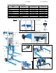
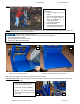
Step 1
: Connect the support legs to the main assembly by following instructions (a) through (e).
Spring-loaded retaining peg
(a) Insert a support leg into each of the
openings in the main assembly.
(b) One at a time, pull the retaining pegs
to allow the legs to slide further into
the openings.
(c) Slowly release the pegs. You may
have to wiggle the leg to get the peg
to drop.
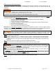
(d) Pull upwards on each of the support
legs to verify that they are held in
place by the pegs. The legs should
not be able to slide out of the opening
(e) If a leg comes out of the opening, the
corresponding peg did not engage
p
ro
p
erl
y
. Re
p
eat
(
a
)
thou
g
h
(
d
)
.
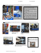
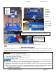
Step 2: Lift the assembly to the upright position (photo a), lock the brakes (photo b) and fasten the winch handle to the
winch body (photos c – f).
Engage the brakes by
pressing down on the
brake actuator
Remove the handle
retaining bolt and washer
(circled)
c
b
a
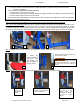
Handle connector
d
Winch body with bolt and
washer removed
Slide the handle onto the
handle connecto
r
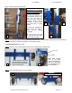
e
f
Set the handle latch pin (circled) to lock the
handle, and then fasten the handle to the
handle connector with the bolt and washer
that you removed in step (c).
Note: Secure the washer against
the bolt head with a nut BEFORE
fastening the bolt to the
connector. to prevent the bolt from
loosening when the handle is
rotated counterclockwise to lower
the forks.
Copyright 2012 Vestil Manufacturing Corp. Page 5 of 12