
Product Manual


rev. 3/20/2013 A-Lift, manual.doc
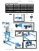
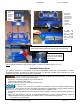
Step 3
: Attach the forks to the carriage.
d
c
Instructions b-d correspond
to steps shown in the
photographs to the right:
b.
A
lign the holes in the
forks with the carriage cross-
bars (11); then push the
forks until they contact the
carriage. Note: It may be
necessary to tap the forks
into place with a rubber
mallet.
c. Slide fork retaining pins
(25) through the holes in
each of the carriage
crossbars.
d. Lock the pins into place
by swinging the ring portion
of each pin downward
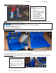
b
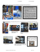
Grasp the
operator handle
(1) with one
hand; turn the
winch handle
clockwise with
the other hand.
Raise the
carriage (10) to a
comfortable work
height.
a
Step 4
: Turn the winch handle counterclockwise to lower the forks. Lower the forks until they are a few inches above
the support legs (22), and then push the lifter to the desired location.
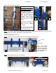
Counterbalanced lifters (A-Lift-CB):
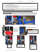
Step 1
: Attach the 5 inch swivel castors (19) to the counterweight base weldment (20).
Lock nut
Bolt
Drop bolts through
each of the holes.
Secure each bolt with a
lock nut. Tighten all of
the connections with a
pair of wrenches.
Turn the weldment over so that
the underside faces upwards.
Align the castors with the bolt
holes in the weldment.
a
b
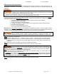
Step 2
: Attach the weldment to the main assembly.
b. Lock both of the castors
a
Copyright 2012 Vestil Manufacturing Corp. Page 6 of 12