
Product Manual


rev. 3/20/2013 A-Lift, manual.doc
2. Debris or other obstructions on the floor/surface;
3. Unsound surfaces or surfaces that cannot support the weight of yourself, the lifter and the load either
together or separately;
Perform the following function test before each use:
1. Test the winch: raise and lower the forks;
2. Test the brakes: press down on the brake actuator to engage the brakes; then attempt to push the lift forward.
3. Test the castors: push the lifter to test the castors.
The end-user bears responsibility for verifying that the lifter complies with all regulations, codes, and standards
that apply in the location where it is used.
Inspect the lifter as recommended in the “Maintenance and Inspection” section of this manual (p. 10). Use the lifter
ONLY IF the lifter passes the inspection and is deemed safe to use by designated inspection personnel
.
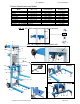
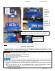
Step 1 (for S and CB Models): Adjust the legs to provide the desired wheel base. Set the brake (-S models) or lock
the castors (-CB models). Remove the forks and lock the carriage using the pivoting carriage latch (photo a). Slowly
tilt the lifter backwards until the loading wheels contact the ground. Pull the leg adjustment peg (photo b) and slide
the leg in the desired direction. Reset the peg in the first or second adjustment setting (photo c) as the job requires.
2
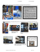
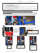
Step 2: Always maneuver the A-lift from the “Operator’s Position” using the Normal Maneuvering Stance shown
below.
Step 3: Move the lifter to a position near the intended load and lock both of the locking castors.
a. G
rasp the
operator handle at
each end. This
will provide the
greatest degree of
steering control.
a
b
c
1
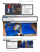
b. W
alk behind the lifter and keep your
feet clear of the castors.
DO NOT place one
foot on the counterweights and propel
the lifter with the other foot. Doing so
will make the lifter more difficult to
control.
a
b
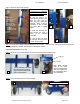
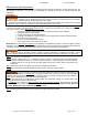
Raise the
forks to a
comfortable
height.
Set the load on the forks.
The load must rest against
the back of the forks.
Lower the forks until
the load is a few
inches above the
adjustable leg (shown
by arrow in photo
above).
Copyright 2012 Vestil Manufacturing Corp. Page 8 of 12