
Product Manual
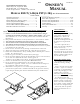
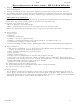
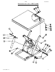
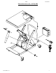
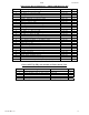


Table Of Contents
- Installation
- Loading and operation
- Battery-powered units' info
- Maintenance and safety checks
- Structural exploded views
- Structural bills of materials
- Motor and transformer connections
- Electrical diagrams
- Hydraulic diagrams
- Power unit operation, valve issues
- Modular power unit parts
- Troubleshooting
- Safety label identification
- Warranty

02/06 24-126-120
V
ESTIL MFG. CO. 2
INSTALLATION INSTRUCTIONS – EHLT (1-4K)
Review this entire page before installing the scissor lift.
Consult the factory in the event there are any questions or problems at the time of installation, or for
information regarding optional features not covered by the owner’s manual.
The scissor lift must be removed from the shipping wood and securely anchored to a concrete surface before use!
• Modifications or additions to the scissor lift without prior manufacturer’s authorization may void the lift’s warranty
(see ANSI MH29.1-2003, Safety Requirements for Industrial Scissor Lifts, Section 12.6). The addition of ancillary
equipment to the lift may necessitate that its load capacity be reduced.
• The installation must be made so that it complies with all the regulations applicable to the machine and its
location. The end-user must verify that the supplied equipment is installed so it will be suited to the environment
in which it will be used.
• Installation must be performed by suitably trained personnel with access to the appropriate equipment. The
electrical aspects of the installation should be performed by an electrician.
Note
: If the unit is to be placed into a pit, you will need to first determine how the required electrical (and possibly
hydraulic) connections will be made once the unit is in place.
---------------------------------------------------------------------------------------
For a typical installation of a standard scissor lift you will need the following:
1. A fork truck or hoisting means to unload the scissor lift from the freight truck and set it into place.
2. A smooth, level, and adequately strong concrete surface on which to mount the scissor lift.
3. Concrete anchors, a masonry drill, a masonry bit, hand tools, grout, and steel shims. Consult the building’s
architect or facility engineer to determine the best size and type of hardware with which to anchor the machine to
the floor.
4. An appropriate power supply circuit and electrical disconnect matching the motor voltage and current
requirements. Refer to the machine’s dataplate, to the labels on the control enclosure, and to the electrical
section in this manual for more information. The end-user is responsible for supplying the branch circuit’s required
ground fault and short-circuit protection. (Motor overload protection is provided by a thermostat built into the
motor.)
---------------------------------------
To install a standard scissor lift:
1. The scissor lift must be lowered and fully supported under its frame when moved. Move the scissor lift into place
with straps or forks that span underneath the entire width or length of the frame. Use care to avoid damage the
electrical or hydraulic components inside the scissor lift.
2. Temporarily connect the power supply to the pigtail cord supplied with the scissor lift, and raise the platform so
the lift’s safety maintenance props can be installed between the legset’s frame rollers and the end of the lift’s
frame. Lower the legset until the rollers rest on the props.
o If the platform must be raised without first having the proper power supply connected, raise the platform at the
end of the table through which the power supply cord enters the frame. Use caution to avoid damage to the
perimeter pinch point (toe) guard! Use a hoist with straps or chain rigging, or insert a lift truck’s forks, at the
hinged end of the platform. Take care to not damage the hanging aluminum toe guard. The frame must be held
down at the ends of the shipping 4 x 4’s on the hinged end of the lift while the platform is raised.
3. Anchor the frame to the floor through the four 9/16” holes located in the frame.
4. Shim and/or grout under the full length of the frame sides.
5. Make permanent connection to the power supply, using an appropriate wiring method.
6. Operate the scissor lift through several full raise and lower cycles. Verify that the upper travel limit switch
(mounted near the left-side frame hinge) and the toe guard switches (around the perimeter of the platform)
function properly.
7. Check the hydraulic oil level. It should be filled to within 1” to 1½” of the reservoir’s fill hole. If oil is needed,
use an anti-wear hydraulic oil with a viscosity grade of 150 SUS at 100°F (ISO 32 at 40°C) or a non-synthetic
automatic transmission fluid.
8. Clean up any debris or spilled oil, and verify that all of the information/safety/warning labels are in good
condition.