
Product Manual
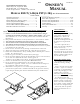
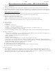
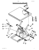
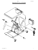
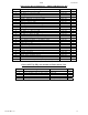


Table Of Contents
- Installation
- Loading and operation
- Battery-powered units' info
- Maintenance and safety checks
- Structural exploded views
- Structural bills of materials
- Motor and transformer connections
- Electrical diagrams
- Hydraulic diagrams
- Power unit operation, valve issues
- Modular power unit parts
- Troubleshooting
- Safety label identification
- Warranty

02/06 24-126-120
V
ESTIL MFG. CO. 3
OPERATION INSTRUCTIONS – EHLT (1-4K) & PST (1-3K)
o Consult ANSI MH29, Section 12 for the owner’s/ user’s responsibilities regarding the operation, care, and
maintenance of this machine.
o Ensure that all employees involved in the operation of this scissor lift understand and follow these instructions!
The standard model scissor lift is suitable for use indoors in most non-classified industrial locations and many
commercial locations. It is intended to be used to lift and transport (PST only) stable, evenly-distributed, non-
hazardous materials loads having a size or footprint approximately the same size as the platform.
Loading:
The load rating, in pounds, is shown on the machine dataplate located on the right corner of the hinged end of the
platform. It indicates the net capacity of the scissor lift with a static load that is centered and evenly distributed on
the platform.
When not fully lowered, the scissor lift’s maximum single axle load is 50% of the rated capacity for side loading, and
75% for end loading. (The hydraulic hose and power cord are at one of the platform’s ends.)
Warning: Do not exceed the scissor lift’s load ratings. Injury to personnel or permanent damage to the lift could result
from exceeding the listed capacity.
Warning: The platform’s rollers are not captured. Therefore, do not overhang any load at the hinged end of the
platform – that could cause the roller end of the platform to tip up and dump the load. For applications involving side
or end edge loading, consult the factory.
Note: The addition of any ancillary equipment to the scissor lift by third parties must be taken into account when
determining the maximum working load to be placed on the platform.
Operation:
Inspect the perimeter pinch point guards’ operation daily.
Warning: Keep all personnel clear of the machine when it is in operation. Be certain no part of any person or object is
under any part of the platform before lowering the unit.
Caution: Always carefully watch the area around the platform and any load on the platform when it is in operation.
The standard model EHLT scissor lift table is furnished with an internally-mounted power unit and a constant-
pressure (dead-man style) handheld pushbutton control.
• Pressing the “UP” pushbutton will turn on the power unit to raise the platform. The platform will raise only while
the pushbutton is pressed. Upon releasing the pushbutton, the platform will stop and hold its position. When the
platform reaches its maximum raised height, an upper travel limit switch will stop the lift from raising further.
• Pressing the “DOWN” pushbutton will energize the lowering valve to allow the platform to descend by gravity (the
motor does not run). Again, releasing the pushbutton will stop the platform movement, and the unit will hold its
position. In the event of an obstruction under the edge of the platform, the perimeter pinch point guard will raise
to engage a switch and thereby de-energize the lowering valve.
Caution: Never use the scissor lift if any damage or unusual noise is observed, if it is in need of repairs, or if it seems
to be malfunctioning. Notify your supervisor or maintenance personnel if you notice anything out of the ordinary.
Units with external, covered, modular power units also have pushbuttons and a key switch in the power unit cover.
The key switch must be turned to the “ON” position for any of the controls to operate.
Standard model PST’s are DC-powered and equipped with a covered, modular power unit having an on-board battery
charger, and the 2-button handheld pushbutton control. It’s operation is the same as the model EHLT.
Warning: before raising the platform from its lowered position, the floor lock must be positively engaged with the
floor. Also, the platform should be fully lowered when a load is being transported. Failure to do so could result in
injury to personnel or damage to product or equipment due to the lift and its load becoming unstable during transport.
Note: attempting to raise the lift when the battery charge is low will cause the motor relay protection circuit to
prevent the motor’s operation. Adequate battery voltage is indicated by a green LED on the motor relay. See the next
page for more notes regarding operation of battery-powered units.
PST’s equipped with the optional two-speed foot pump are operated by repeatedly stepping on the foot pump
treadle to raise the platform, and by stepping on the smaller release pedal on the left corner of the foot pump body to
lower the platform. The pump’s output (and therefore the lifting rate) can be changed by means of a slider at the top
of the foot pump. The low-speed output must be used when the platform is loaded.
Ensure that all information/safety/warning labels stay in place and are legible. Refer to the labels page in this
manual.