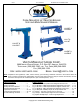
01/11 rev. 3/12/2013 LM-series fork-mountable booms FORK-MOUNTED LIFT MASTER BOOMS USE AND MAINTENANCE MANUAL LM-OBT & LM-OBNT LM-1T & LM-1NT LM-HRT & LM-HRNT LM-EBT & LM-EBNT VESTIL MANUFACTURING CORP. 2999 NORTH WAYNE STREET, P.O. BOX 507, ANGOLA, IN 46703 TELEPHONE: (260) 665-7586 -OR- TOLL FREE (800) 348-0868 FAX: (260) 665-1339 URL: WWW.VESTILMFG.COM EMAIL: SALES@VESTIL.
LM-series fork-mountable booms 01/11 PRODUCT INTRODUCTION Thank you for purchasing a fork-mounted Lift Master boom (“boom”, “product” or simply “LM”) made by Vestil Manufacturing Corporation (“Vestil”). Our booms are durable, high-quality products that combine safety-conscious design features and rigorous engineering.
LM-series fork-mountable booms 01/11 Vestil manufactures 5 models of Lift Master booms. The 5 variants are distinguishable by boom length, whether the boom length is adjustable or fixed, and maximum rated load. Each unit conforms to the generalized specifications disclosed in this manual and fulfills our demanding standards for quality, safety and durability. Vestil Manufacturing Corp. recognizes the critical importance of workplace safety.
LM-series fork-mountable booms 01/11 DO NOT use the boom if any product label (see p. 24) is unreadable, damaged, or absent. Contact Vestil to order a replacement label(s). ALWAYS apply proper (fork) lift operation practices learned during your training program. Before raising the boom from the floor AND before attaching the load to the boom, tilt the fork lift mast away from the boom to ensure that the boom will not slide towards the tips of the forks.
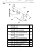
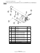
01/11 rev. 3/12/2013 LM-series fork-mountable booms FIG. 1A: EXPLODED PARTS DIAGRAM & PARTS LIST FOR LM-1T-4K, 6K, & 8K MODELS 7 9 3 4 1 8 5 6 10 2 11 Item No. 1 2 3 Part No.
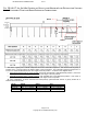
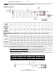
LM-series fork-mountable booms 01/11 FIG. 1B: LM-1T- 4K, 6K & 8K CENTERS OF GRAVITY AND MAXIMUM LOAD RATINGS FOR VARYING LOAD ATTACHMENT POINT AND BOOM EXTENSION COMBINATIONS EHCG FIG. 1B: LM-1T- 4K, 6K & 8K CENTERS OF GRAVITY AND MAXIMUM LOAD RATINGS VARYING LOAD ATTACHMENT POINT AND BOOM EXTENSION COMBINATIONS FORVCG VCG RHCG RHCG The center of gravity has a vertical component as well as a horizontal component. The vertical center of gravity is located 15.5 in. (~39.
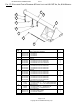
LM-series fork-mountable booms 01/11 FIG. 1C: EXPLODED PARTS DIAGRAM & PARTS LIST FOR LM-1NT-4K, 6K, & 8K MODELS 8 3 5 4 7 1 9 6 2 10 Item No. 1 2 3 Part No.
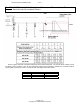
LM-series fork-mountable booms 01/11 FIG. 1D: LM-1NT- 4K, 6K & 8K CENTERS OF GRAVITY VARYING LOAD ATTACHMENT POINTS AND MAXIMUM LOAD RATINGS FOR HCG VCG Center of gravity has both a horizontal component and a vertical component. The vertical center of gravity (VCG) lies along a line 15.5 inches (~39.4 cm) from the bottom edges of the fork pockets. Similarly, the horizontal center of gravity (HCG) is located 31 inches (~79 cm) from the outer edges of the fork pockets.
LM-series fork-mountable booms 01/11 FIG. 2A: EXPLODED PARTS DIAGRAM & PARTS LIST FOR LM-OBT-4K, 6K, & 8K MODELS 7 5 1 6 3 4 2 8 Item No. 1 2 3 9 Part No. 08-514-119 08-514-122 08-514-125 08-145-008 08-145-010 08-145-004 08-145-006 4 08-145-009 08-145-002 08-145-005 5 08-145-003 08-145-004 6 7 8 9 08-145-001 08-145-002 08-146-002 99-145-025 13-025-003 Description Boom, base frame weldment LM-OBT-4k LM-OBT-6k LM-OBT-8k Snap hook Shackle LM-OBT-4k: 2-ton max. rated load LM-OBT-6k: 3-ton max.
LM-series fork-mountable booms 01/11 FIG. 2B: LM-OBT- 4K, 6K & 8K CENTERS OF GRAVITY AND MAXIMUM LOAD RATINGS FOR VARYING LOAD ATTACHMENT POINT AND BOOM EXTENSION COMBINATIONS RHCG VCG EHCG LM-OBT-4k LM-OBT-6k LM-OBT-8k The center of gravity has a vertical component as well as a horizontal component. The vertical center of gravity is located 13 in. (~33 cm) above the bottom edges of the fork pockets.
LM-series fork-mountable booms 01/11 FIG. 2C: EXPLODED PARTS DIAGRAM & PARTS LIST FOR LM-OBNT-4K, 6K, & 8K MODELS 1 7 5 6 3 4 9 2 8 Item No. 1 2 3 Part No. 08-514-132 08-514-135 08-514-136 08-145-008 08-145-010 08-145-004 08-145-006 4 08-145-009 08-145-002 08-145-005 5 08-145-003 08-145-004 08-145-004 6 7 8 9 08-145-001 08-145-002 08-145-002 08-146-002 99-145-025 13-025-003 Description Boom, base frame weldment LM-OBNT-4k LM-OBNT-6k LM-OBNT-8k Snap hook Shackle LM-OBNT-4k: 2-ton max.
LM-series fork-mountable booms 01/11 FIG. 2D: LM-OBNT- 4K, 6K & 8K CENTERS OF GRAVITY AND MAXIMUM LOAD RATINGS FOR VARYING LOAD ATTACHMENT POINTS HCG VCG = 15 in. VCG m) (~38c Center of gravity has both a horizontal component and a vertical component. The vertical center of gravity (VCG) lies along a line 15 inches (~38 cm) from the bottom edges of the fork pockets. Similarly, the horizontal center of gravity (HCG) is located 35-7/8 inches (~91 cm) from the outer edges of the fork pockets.
LM-series fork-mountable booms 01/11 FIG. 3A: EXPLODED PARTS DIAGRAM & PARTS LIST FOR LM-HRT-4K & 6K MODELS 3 4 5 6 7 2 1 8 Item No. 1 2 3 4 Part No. 08-514-005 08-514-006 08-145-008 08-025-004 08-145-003 08-145-004 5 08-145-001 08-145-002 6 08-145-010 08-145-004 7 8 08-145-009 08-145-002 99-145-025 Description Boom, base frame weldment LM-HRT-4k LM-HRT-6k Snap hook X-handle locking bolt Shackle LM-HRT-4k: 2-ton max. rated load LM-HRT-6k: 3-ton max. rated load Load hook LM-HRT-4k: 2-ton max.
LM-series fork-mountable booms 01/11 FIG. 3B: LM-HRT- 4K & 6K CENTERS OF GRAVITY AND MAXIMUM LOAD RATINGS VARYING LOAD ATTACHMENT POINT AND BOOM EXTENSION COMBINATIONS FOR VCG Model LM-HRT-4k LM-HRT-6k EHCG 3 in. (~7.6 cm) 3 in. (~7.6 cm) RHCG 8 in. (~20 cm) 8 in. (~20 cm) VCG 38 in. (~97 cm) 38 in. (~97 cm) EHCG RHCG The center of gravity has a vertical component as well as a horizontal component.
LM-series fork-mountable booms 01/11 FIG. 3C: EXPLODED PARTS DIAGRAM & PARTS LIST FOR LM-HRNT-4K & 6K MODELS 3 5 4 6 1 2 7 Item No. 1 2 3 Part No. 08-514-007 08-514-022 08-145-008 08-145-003 08-145-004 4 08-145-001 08-145-002 5 08-145-010 08-145-004 6 7 08-145-009 08-145-002 99-145-025 Description Boom, base frame weldment LM-HRNT-4k LM-HRNT-6k Snap hook Shackle LM-HRNT-4k: 2-ton max. rated load LM-HRNT-6k: 3-ton max. rated load Load hook: LM-HRNT-4k: 2-ton max. rated load LM-HRNT-6k: 3-ton max.
LM-series fork-mountable booms 01/11 FIG. 3D: LM-HRNT- 4K & 6K CENTERS OF GRAVITY VARYING LOAD ATTACHMENT POINTS AND MAXIMUM LOAD RATINGS FOR = Center of gravity Center of gravity has both a horizontal component and a vertical component. The vertical center of gravity (VCG) lies along a line 38 inches (~97 cm) from the bottom edges of the fork pockets. Similarly, the horizontal center of gravity (HCG) is located 8 inches (~20cm) from the front edge of the vertical support.
LM-series fork-mountable booms 01/11 FIG. 4A: EXPLODED PARTS DIAGRAM & PARTS LIST FOR LM-EBT-4K, 6K & 8K MODELS 2 3 1 4 5 6 7 Item No. 1 2 3 Part No. 08-514-001 08-514-028 08-514-192 08-025-004 08-145-003 08-145-004 08-145-004 4 08-145-001 08-145-002 08-145-002 5 08-145-010 08-145-004 08-145-006 6 7 08-145-009 08-145-002 08-145-005 08-145-028 99-145-025 Description Boom, base frame weldment LM-EBT-4k LM-EBT-6k LM-EBT-8k X-handle locking bolt Shackle LM-EBT-4k: 2-ton max.
LM-series fork-mountable booms 01/11 FIG. 4B: LM-EBT – 4K, 6K & 8K CENTERS OF GRAVITY AND MAXIMUM LOAD RATINGS FOR VARYING LOAD ATTACHMENT POINT AND BOOM EXTENSION COMBINATIONS Outer edges of fork pockets EHCG VCG RHCG The center of gravity of the boom ranges between a minimum of 34.5 inches and a maximum of 54.5 inches from the outer edges of the fork pockets.
LM-series fork-mountable booms 01/11 FIG. 4C: EXPLODED PARTS DIAGRAM & PARTS LIST FOR LM-EBNT-4K, 6K & 8K MODELS 1 7 5 6 3 4 2 8 Item No. Part No. 1 2 Description Quantity 08-514-003 08-514-004 08-514-191 Boom, base frame weldment LM-EBNT-4k LM-EBNT-6k LM-EBNT-8k 1 1 1 08-145-008 Snap hook 1 3 08-145-003 08-145-004 08-145-004 4 08-145-001 08-145-002 08-145-002 5 08-145-010 08-145-004 08-145-006 6 7 9 08-145-009 08-145-002 08-145-005 99-145-025 Shackle LM-EBNT-4k: 2-ton max.
LM-series fork-mountable booms 01/11 FIG. 4D: LM-EBNT- 4K, 6K & 8K CENTERS OF GRAVITY FOR VARYING LOAD ATTACHMENT POINTS AND MAXIMUM LOAD RATINGS HCG VCG Center of gravity has both a horizontal component and a vertical component. The vertical center of gravity (VCG) lies along a line 15 inches (~38 cm) from the bottom edges of the fork pockets. Similarly, the horizontal center of gravity (HCG) is located 35-7/8 inches (~91 cm) from the outer edges of the fork pockets.
LM-series fork-mountable booms 01/11 FIG. 5A: EXPLODED PARTS DIAGRAM & PARTS LIST FOR LMS-EBT-46-4, 6 & 8 MODELS 2 Item No. 71 1 Part No. Description 08-145-008 Snap hook 2 08-025-004 X-handle locking bolt 3 1 3 4 5 4 5 6 6 8 7 8 08-145-003 08-145-004 08-145-004 08-145-001 08-145-002 08-145-002 08-145-010 08-145-004 08-145-006 08-145-009 08-145-002 08-145-005 08-514-194 08-514-195 08-514-202 99-145-025 Shackle LMS-EBT-46-4: 2-ton max. rated load LMS-EBT-46-6: 3-ton max.
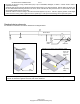
LM-series fork-mountable booms 01/11 Operation Instructions: Review “Safety Guidelines” on p. 2-3 before using the boom. 1. Insert fork truck tines into the fork pockets and drive as far forward as possible; then lower the forks completely. The drawings below demonstrate this step: Fig.
LM-series fork-mountable booms 01/11 4. [OBT models] Adjust the boom angle: a. 1 person must grasp the red pitch handle with one hand b. while the other person pulls out the locking pin; then c. both persons press down on the angle-adjusting handle until the desired angle is achieved; d. The person who removed the locking pin should reinsert the pin through the openings in the adjustment brackets and through the locking pin channel. Fig.
LM-series fork-mountable booms 01/11 Test the stability of the load attachment. Raise the forks slowly to minimize load movement. Raise the forks until the load is entirely suspended from the boom. Watch the load and boom closely for either of the following issues: 1. Load sliding in rigging; or 2. Boom sliding towards tips of forks. If you notice either #1 or #2 occurring, immediately lower the forks until the load is completely supported by the ground; then adjust the rigging.
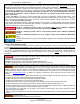
LM-series fork-mountable booms 01/11 Inspections & Maintenance: Inspection and maintenance personnel should immobilize the boom before either conducting inspections or performing maintenance. The boom is properly immobilized if it cannot tip over. If one or more problem is discovered during an inspection, restore the boom to normal operating condition BEFORE using it again. DO NOT use a boom that is structurally damaged in any way.
LM-series fork-mountable booms 01/11 Loose bolts or rivets. Worn, cracked or distorted parts such as pins, shackles, hooks. Boom not in regular use: For each of the 3 bullet points below, in addition to the inspections, any boom, which has been idle for a period of a month or more due to shutdown or storage of the boom, must be given a thorough inspection before it is used again.
LM-series fork-mountable booms 01/11 Product markings & labels Label #278 Label #203-2 Label #287 Label #577 (applied to both sides of boom) Label #525 Page 27 of 27 Copyright 2013 Vestil Manufacturing Corp.