
User`s manual


User’s Manual 9
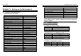
J1: Power Supply Connector 2 pin wafer (3.96mm)
Pin No. Function Pin No. Function
1 +12V 2 GND
JUSB1 JUSB2: Box Header Type Connector for USB port (2.54mm)
Pin No. Function Pin No. Function
1
USB_VCC
2
USB_VCC
3
USBD2-/4-
4
USBD3-/5-
5
USBD2+/4+
6
USBD3+/5+
7
USB_GND
8
USB_GND
9
USB_GND
10
USB_GND
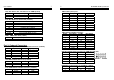
CD_IN1: CD IN Box Header Connector (2.54mm)
Pin No. Function Pin No. Function
1 LEFT 2 GND
3 GND 4 RIGHT
SPDIF: SPDIF Box Header Connector (2.54mm)
Pin No. Function
1
+5V
2
N.C.
3
SPDIFOUT
4
GND
JP11: DIGITAL I/O Box Header Connector (2.54mm)
Pin No. Function Pin No. Function
1 DIO-O0 2 DIO-I0
3 DIO-O1 4 DIO-I1
5 +12V 6 +12V
7 KEY 8 +5V
9 GND 10 GND
11 DIO-O2 12 DIO-I2
13 DIO-O3 14 DIO-I3
Note: When use UC-COM56 kit, pin 1~pin 10 of JP11 will redirect to J2 on
UC-COM56. Attention to level at the box header of JP11 & JP5 when
you plug UC-COM56.
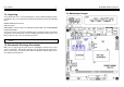
10 The ENDAT-3400M System Board
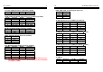
FAN1, FAN2: CPU / 2nd Cooling Fan Connector
Pin No. Function
1
GND
2
+12V
3
Sensor Pin
D-SUB Type Connector for COM1/2 port (RS-232)
Pin No. Description Pin No. Description
1
DCD
6
DSR
2
RXD
7
RTS
3
TXD
8
CTS
4
DTR
9
RI
5
GND
D-SUB Type Connector for COM2 port (RS-422Æ 4 Wire)
Pin No. Function Pin No. Function
1
–TXD
6
NA
2
+RXD
7
NA
3
+TXD
8
NA
4
NA
9
–RXD
5
NA
D-SUB Type Connector for COM2 port (RS-485Æ 2 Wire)
Pin No. Function Pin No. Function
1
Data –
6
NA
2
NA
7
NA
3
Data +
8
NA
4
NA
9
NA
5
NA
J2: SM Bus
Pin No. Function Pin No. Function
1
SMBCK
3
+3.3V
2
SMBDT
4
GND