Valco Instruments Co. Inc. Dynacalibrator Model 235 Instruction Manual Manufactured by: Valco Instruments Co. Inc. 8300 Waterbury Houston, TX 77055 8/13 North America, South America, and Australia/Oceania contact: Valco Instruments Co. Inc. 800 · 367· 8424 713 · 688· 9345 713 · 688· 8106 valco@vici.com sales tech fax Europe, Asia, and Africa contact:: VICI AG International Schenkon, Switzerland Int + 41 · 41 · 925· 6200 Int + 41 · 41 · 925· 6201 info@vici.
Symbols used in this document Attention Radiant heat warning Entanglement warning Electrical warning
Table of Contents Introduction General Description.......................................................................................................................... 1 Dynacal® Permeation Devices....................................................................................................... 1 How to Use This Manual.................................................................................................................. 1 Basic Design.....................................................
If this equipment is used outside manufacturers’ specification the protection provided by the equipment may be impaired.
1 Introduction General Description VICI Metronics Dynacalibrators® use Dynacal® permeation devices to generate the precise gas concentrations necessary for calibrating air pollution analyzers, monitors, and other instruments that measure gas concentrations in the partsper-million range and lower. Dynacalibrators are available in three models, each with a large variety of optional features to fit a wide range of calibration requirements.
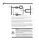
Introduction 2 Figure 1: Model 235 plumbing schematic The Model 235 has no valves to redirect the flows in a manner which would provide a zero setting for this instrument. The dilution stream and carrier streams pass through the mixing tee at all times.
Introduction 3 Specifications
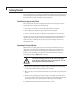
4 Getting Started Every Dynacalibrator is completely calibrated, thoroughly tested and inspected, and carefully packed prior to shipment. The carrier has assumed responsibility for its safe delivery upon acceptance of the shipment. Initial Receiving Inspection/Check On receipt of your unit, before signing the waybill and releasing the carrier’s agent, inspect the shipment for the following: 1. The number of cartons received tallies with that on the waybill. 2.
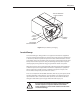
Getting Started 5 Figure 2: Dynacalibrator packaging Concealed Damage Concealed damage is damage which is not apparent until after the equipment has been unpacked and examined or tested. In the event that concealed damage is discovered, a written request for inspection must be forwarded to the carrier’s agent within 15 days of the delivery date.
Getting Started 6 Unit Location In general, the Dynacalibrator should be as close as possible to the analyzer to be calibrated, as long as: • the ambient temperature is at least 2°C below the selected operating temperature of the permeation chamber. • ambient temperature variations are minimal. • exposure to precipitation and condensation is minimized. • air flow around the unit’s cooling vents and rear panel fan intake is not blocked or restricted, particularly for the rack-mounted units.
Getting Started 7 Rear Panel Connections Remove all shipping caps and shipping plugs from the rear panel bulkhead fittings. All these hardware items should be saved for reuse if the Dynacalibrator must be stored or returned to VICI. Fitting locations are identical for all configurations. Fitting holes which are not used are equipped with blank caps. All connections are clearly marked and easily identified. Supply Inlet All Model 235 Dynacalibrators are equipped with a supply inlet fitting.
Getting Started 8 Span Outlet The primary outlet on the Model 235 is labeled SPAN OUT. The SPAN OUT port may be either permanently plumbed to the calibrate input port of an analyzer or temporarily connected to its sample input for calibration, depending on the capabilities of the analyzer. NOTE: The Span Out port should be directly connected to the analyzer input with a minimum length of tubing. Altering the output stream in any manner may affect the concentration of calibration gas in the stream.
Getting Started 9 OVEN TEMPERATURE UPPER LIMIT A power-limiting thermostat provides a safety shutoff at this user-defined setpoint, usually 5-10 degrees above the normal run temperature of the permeation device in use. . If the oven runs out of control, or if a temperature setpoint is requested that is above the temperature limit, power to the oven heater is shut down and a “PFAIL” warning will indicate the need to check the temperature setpoint and cycle the power to reset the device.
10 Initial Set-Up Connections 1. Plug the supplied power cord into the rear mounted power supply. Ensure that the power supply output cable is plugged into the interface board power connector. 2. Remove caps from the SUPPLY INLET, SPAN OUT, and OVERFLOW VENT ports on the rear panel. (Figure 3) 3. Connect the clean, dry, regulated supply gas source (25 psig min, 50 psig max) to the carrier inlet on the rear panel.
Initial Set-Up 11 ready status light Figure 5: Model 235 Manual screen NOTE: The Ready status light will be red while the oven is changing temperature. Once the oven temperature is within the control limits, the status indicator will change to green. Setting the Oven Temperature Limit A mechanical thermostat is integrated with the temperature control circuit for fail-safe temperature control to a limit set on the front panel.
Initial Set-Up 12 5. Turn off the power switch and wait 15-20 minutes for the chamber to cool. 6. Turn on the heater power switch and set the chamber operating temperature. When PFAIL occurs, the Dynacalibrator must be turned off long enough for the chamber to cool before the power is turned back on. Installing the Permeation Device(s) 1. Reduce the temperature setpoint for the permeation chamber to 30°C.
Initial Set-Up 13 Configuration The Model 235 has been designed to provide high accuracy dilution of permeated gases in both automatic and manual operation modes with minimal configuration. The input necessary to configure the instrument is accomplished on two screens, the Setup and Tubes screens. The specifics for each permeation device and the time, date and units of measure are all that is required for configuration.
Initial Set-Up 14 Tubes Screen Select the Tubes screen by touching the “Tubes” tab on the left hand side of the display. On this screen, the following parameters are established: Compound To select the correct compound: 1. Touch the white area of the Compound text field to open the pull down menu. 2. Scroll down to select the desired compound. The pull down menu will disappear and the compound name will update in the Compound textbox.
15 Basic Operation Important Permeation Device Considerations • If more than one tube is to be used in the oven at the same time, order all the tubes with permeation rates given at the same temperature. • Certified permeation devices should be used only at the temperature specified on the certificate. • Using any permeation device beyond its recommended temperature range could result in the destruction of the device by explosion and/or changes in the membrane characteristics.
Basic Operation 16 once data is entered, select enable to save the changes Figure 9: Model 235 Manual screen Once the correct values are input in the correct fields, select the "Enable” button on the lower right hand portion of the Manual screen. If this Enable step is omitted, the changes will be lost when you navigate to another screen. NOTE: When changes to this screen are made and enabled, the Status indicator will be red for a preset period of time.
Basic Operation 17 once data is entered, select enable to save the changes Figure 10: Model 235 Auto screen 4. Select the particular tube to be used as the basis for calculations by touching on the tube name. The pull down will roll up and the selected entry will occupy the text box labeled “Compound”. As soon as the tube is selected, the Concentration Range line will be populated with the minimum and maximum concentration available with this tube. 5.
Basic Operation 18 Status indicator A red indicator means Not Ready, which can reflect one or more of the following: • Flow outside of tolerances • Temperature outside of tolerances • Equilibration period not satisfied NOTE: The equilibration period does not begin until the instrument meets all criteria for a Ready status. Therefore the Ready status (green) will not appear until a preset time after the initial achievement of the Ready requirements. The equilibration period for Flow is five minutes.
Basic Operation 19 Figure 12: Model 235 Graph screen (Flow) select from the installed devices, and the graph will update with the historical data of the selected device. Use your finger to scroll from right to left along the line. As the cursor moves, the exact measurements of each point will be displayed, along with the date and time of the recording of that data point. Flow Select the Flow button to display the total flow logged for the instrument on a 10 hour, 24 hour, or 7 day graph.
20 Analyzer Calibration When the power-up procedure is completed and the chamber temperature, flow, and permeation device have reached equilibrium, the system status indicator in the lower left hand corner of the display will give a "Ready" (green) status. This indicates that the Dynacalibrator is ready to be connected to the analyzer to be calibrated. Use a minimum length of tubing for the connection, and ensure that all of the Dynacalibrator’s vents are open.
21 Shutdown Procedure Dynacalibrators are designed to operate continuously; however, if it is necessary to turn the unit off, use the following procedures: 1. On the Manual screen, set the Temp to 30, and select the “Enable” button. 2. Allow the oven to equilibrate at this temperature 3. With the tool provided, rotate the oven door lock screw 90° counterclockwise. 4. Gently pull the front panel assembly out. CAUTION: Use specific and appropriate precaution when opening the calibrator oven.
22 Advanced Theory of Operation Dynacalibrator operation is based on the principle of mixing a known mass flow of gas permeation device with a metered stream of clean carrier/dilution gas to generate a precise concentration of span gas. User-selectable calibration gases originate from Dynacal permeation devices which are maintained at a user-selectable constant temperature within the Dynacalibrator’s permeation chamber.
23 Electrical Description Dynacalibrators are powered from a benchtop style transformer on the rear panel. This is a switcher-style supply that allows a range of input voltage and frequency from 100 to 240 VAC at 50-60 Hz. The power supply steps the voltage down and regulates the output to 24 VDC. If the cord end type is inappropriate for your locale, please contact VICI for a replacement cord. The main power switch is on the front panel.
24 Maintenance Since Dynacalibrators are designed for and generally used in applications that require continuous service, a planned routine maintenance program is highly recommended. Routine maintenance consists of inspection, cleaning, calibration, and leak checks. The table below lists the recommended checks and maintenance frequencies for continuous and non-continuous use.
Maintenance 25 9. Rinse the fan screen and fan filter in clean water and blow dry with lowvelocity air. 10. Reinstall the fan, fan filter, fan screen brackets, and fan screen using the four screws, lockwashers, and hex nuts. 11. Replace the top cover of the unit and return it to service according to the procedures on page 10.
26 Model Number Breakdown
27 Warranty This Limited Warranty gives the Buyer specific legal rights, and a Buyer may also have other rights that vary from state to state. For a period of 90 calendar days from the date of shipment, VICI Metronics Inc. (hereinafter Seller) warrants the goods to be free from defect in material and workmanship to the original purchaser.