
Install Instructions


10 | PIR Ready VT7600 Series-Installation Guide
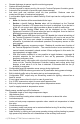
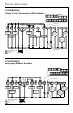
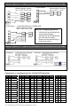
WIRING EXAMPLES OF 2 REMOTE ROOM SENSORS FOR AVERAGING APPLICATIONS:
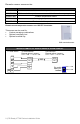
WIRING EXAMPLES OF 3 REMOTE ROOM SENSORS FOR AVERAGING APPLICATIONS:
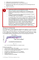
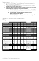
Temperature vs. resistance chart for 10 Kohm NTC thermistor
ºC ºF Kohm ºC ºF Kohm ºC ºF Kohm ºC ºF Kohm ºC ºF Kohm
-40 -40 324.3197 -20 -4 94.5149 0 32 32.1910 20 68 12.4601 40 104 5.3467
-39 -38 303.6427 -19 -2 89.2521 1 34 30.6120 21 70 11.9177 41 106 5.1373
-38 -36 284.4189 -18 0 84.3147 2 36 29.1197 22 72 11.4018 42 108 4.9373
-37 -35 266.5373 -17 1 79.6808 3 37 27.7088 23 73 10.9112 43 109 4.7460
-36 -33 249.8958 -16 3 75.3299 4 39 26.3744 24 75 10.4443 44 111 4.5631
-35 -31 234.4009 -15 5 71.2430 5 41 25.1119 25 77 10.0000 45 113 4.3881
-34 -29 219.9666 -14 7 67.4028 6 43 23.9172 26 79 9.5754 46 115 4.2208
-33 -27 206.5140 -13 9 63.7928 7 45 22.7861 27 81 9.1711 47 117 4.0607
-32 -26 193.9703 -12 10 60.3980 8 46 21.7151 28 82 8.7860 48 118 3.9074
-31 -24 182.2686 -11 12 57.2044 9 48 20.7004 29 84 8.4190 49 120 3.7607
-30 -22 171.3474 -10 14 54.1988 10 50 19.7390 30 86 8.0694 50 122 3.6202
-29 -20 161.1499 -9 16 51.3692 11 52 18.8277 31 88 7.7360 51 124 3.4857
Notes for averaging applications:
• S3010W1000 and S3020W1000
can be mixed matched.
• S3010W1000 and S3020W1000
are to be wired in parallel.
• Respect the dip switch setting in
each remote sensor.
AU
D1
RS
Scom
C
D2
Scom
RS
Scom
RS
C
DI
Aux
Scom
RS
Scom
RS
C
DI
Aux
AU
D1
RS
Scom
C
D2
Scom
RS
Scom
RS
Scom
RS
Scom
RS
C
DI
Aux
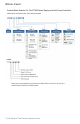
VT7600 Series
2x S3020W1000
Remote wiring 2 sensors
S2-1 = OFF / S2-2 = ON
AU
D1
RS
Scom
C
D2
Scom
RS
Scom
RS
Scom
RS
Scom
RS
2x S3010W1000
Remote wiring 2 sensors
S
2-1 =
O
FF
/
S
2-2 =
VT7600 Series
VT7600 Series
1x S3010W1000 and 1x S3020W1000
Remote wiring 2 sensors
S2-1 = OFF / S2-2 = ON