
Install Instructions


7 | PIR Ready VT7600 Series-Installation Guide
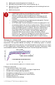
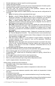
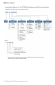
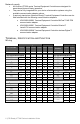
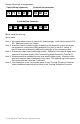
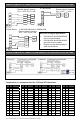
Screw terminal arrangement
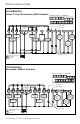
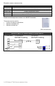
Main outputs wiring
Wiring notes:
Note 1: If the same power source is used for the heating stages, install jumper across RC &
RH. Maximum current is 2.0 amps.
Note 2: If auxiliary output is used to toggle occupancy of the electronic control card inside
the equipment, configure the relay parameter (Aux cont) to the N.O. setting. A
second relay can be added for additional functionality of the occupancy output.
Note 3: Economizer output uses a half bridge rectifier. Reference of the control signal is the
common of the power supply of the Terminal Equipment Controller. (Terminal C)
Note 4: Electromechanical contacts are to be used with the digital inputs. Electronic triacs
cannot be used as mean of switching for the input. The switched leg to the input for
the input to activate is terminal C (common)
Note 5: The transformer of the unit provides power to the t Terminal Equipment Controller
and the additional loads that will be wired to the Terminal Equipment Controller.
EC AU
D1
D2 RS
Scom
OS MS
Y
2
Y
1 G RC C
RH W1
W2
O/B
5 pole left top connector
3 pole left top connector
8 pole bottom connector