
User Manual

UG:100 vicorpower.com Applications Engineering: 800 927.9474 Page 2
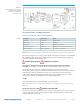
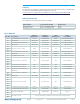
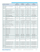
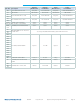
Basic Specifications and Operating Limits
Please use the following table for operating limits:
Description Specification Notes
Input range 85 – 264 Vac Universal input
Output voltage 48 Vdc Regulated
Output power 330 W Over entire input range
Operating temperature -40 to 85°C Limited by C37, T01-T03, U01, Z01-Z04
Output capacitance 6,000 to 12,000 μF 63 V rating, 20% tolerance
NOTE: Module operating temperature will depend on its Product Grade as specified in the data sheet.
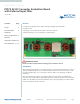
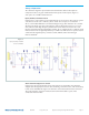
Please refer to Figure 1 for locations of the input and output connections as viewed from
the component side. Wires may be soldered directly to the pads instead of ring lugs if
desired to minimize circuit impedances.
DANGER! HIGH VOLTAGE! DANGER! HOT SURFACE!
The VI Brick
®
AC-DC Converter Evaluation Board contains exposed hazardous
voltages. These voltages are within the area marked by the letter H on the PCB.
The VI Brick DC-DC Converter Evaluation Board may be operated at surface
temperatures which may pose a thermal hazard to the operator. Because of the thermal
and voltage hazards, be careful not to touch any exposed surface unless the power
is disconnected and the evaluation board has been given sucient time to cool. The
evaluation board is not intended for use in end item equipment.
Set Up
The Customer Evaluation Board should be set up as follows:
Note: Care should be taken to avoid reversing polarities if connecting to the opposite (solder) side of
the board.
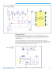
AC Input Connections (J01) DANGER! HIGH VOLTAGE!
J01, the screw terminal connector, is for connection of AC input to the AC-DC converter
evaluation board. The interconnect leads should be appropriate for the current and
voltage supplied to the board.
Table 1.
Figure 1.
VI Brick PFM AC DC Converter
Evaluation Board layout
and dimensional drawing,
component side