
User Manual

UG:100 vicorpower.com Applications Engineering: 800 927.9474 Page 3
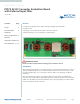
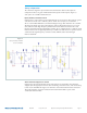
For single phase power, connect LINE to the pin marked L, NEUTRAL to the pin marked
N and earth ground to the pin marked EARTH. Corresponding wires in an IEC cable are
brown, blue, and yellow with a green stripe.
The board can be used with three phase power. Connect LINE1 to L and LINE2 to N.
Earth ground should still be connected to the EARTH terminal of J1.
+OUT, –OUT
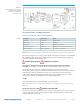
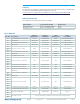
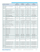
There are several connections available on the VI Brick AC-DC converter. Table 1 lists
the available connectors and their current rating. Do not exceed the rating of the
connector or the AC-DC converter.
Connector Rating Recommended Connection
J02 10 A Hold-up capacitor
J03 12 A (3 A/contact) Mating PRM and BCM eval boards
Ring lugs 100 A EARTH, +OUT, -OUT
2 mm holes beside C37 12 A Snap-in type capacitor 10 mm sp
Output bulk (electrolytic) capacitance must be attached across the output of the
VI Brick® AC-DC converter evaluation Board. Refer to the table above for the
appropriate range of output capacitance.
The load should be connected to +OUT and –OUT terminals of the evaluation board
with short leads of suitable gauge to carry the output current and minimize losses. A
sucient number of terminal connections should be used to ensure that no terminal
sees more than its maximum rated current. The evaluation board can be connected
directly to the application for which the AC-DC converter is intended. However the
interconnect impedances between the evaluation board and the application can greatly
aect the transient response. For applications where transient response is critical, the
user should consider mounting the VI Brick AC-DC converter directly to the target
application PCB.
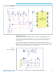
Earth Connections
There is one EARTH connection available on the board, in the lower le hand corner,
P01 in the schematic diagram. The EARTH connection used for local return for the EMI
filter is the same as safety ground.
EARTH may optionally be connected to either of the AC-DC converter outputs in order
to provide a positive or negative voltage rail with respect to earth.
The default configuration of the evaluation board is to have the EARTH terminal
connected to –OUT through jumper JP02, while JP03 is unpopulated. To leave the
outputs floating, remove JP03 so that both JP02 and JP03 are unpopulated. To connect
EARTH to +OUT, remove JP02 and populate JP03.
The insulation of the AC/DC converter modules supported by this evaluation board
has not been designed to exceed SELV voltages, and should not exceed +/-60Vdc from
EARTH potential by stacking.
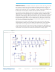
Input Current Measurement
A current probe can be passed around either input lead connected to the VI Brick
evaluation board. This can be used to measure DC currents and AC currents in front of
the EMI filter and transient suppression circuits.
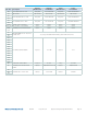
Table 2.
Output Connector Ratings