
User Manual

UG:100 vicorpower.com Applications Engineering: 800 927.9474 Page 4
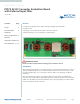
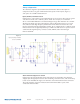
Output Voltage Measurement Jack (J12)
This connector is provided to make accurate measurements of the output ripple
voltage of the VI Brick® AC-DC converter. Many types of scope probes may be directly
connected to this point if the probe is equipped with a removable plastic sheath. To
avoid creating ground loops when making measurements of the output or input
voltage, these measurements should be made separately. Clamp on ferrite chokes, such
as Digikey PN 240-2132-ND placed over the leads of passive oscilloscope probes also
help to reduce common mode high frequency switching noise pickup. A capacitor can
be added at C29 to reduce high frequency noise at the probe if necessary.
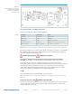
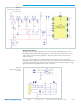
Enable (EN) DANGER! HIGH VOLTAGE!
The EN pin can be used to disable the VI Brick AC-DC converter. Connecting EN to
the –IN-PFM pin will disable the AC-DC converter. This will also clear any latching
output OVP fault if one has occurred. Note that the EN pin is referenced to the primary
(hazardous voltage) side of the converter. The EN pin can be accessed from J04, for
which a mating connector can be used. The mating connector is Molex P/N 43645-0500
with Molex 43030 series pins.
An optocoupler has been provided to allow connection to output referenced equipment.
The input to the optocoupler is connected to –OUT by default. Jumper JP04 can be
removed, allowing the customer to provide their own reference for the enable input.
This input can be floated up to +/-1000V from EARTH.
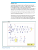
Efficiency Measurement
As the VI Brick AC-DC Converter can deliver and consume large currents, the eect of
the PCB must be considered when making an eciency measurement. When testing
your design based on this reference design, be sure to probe dierent points in the input
filter and rectifier section to verify that voltage drops are not excessive in your layout.
If eciency tests are to be automated, then Kelvin type connections are recommended
to reduce common current errors during voltage measurements.
Recommended Hardware
The hardware kit provided with the evaluation board includes the following:
n 6 #10 lock washers
n 3 #10-32 screws
n 3 #10-32 hex nuts
Ring lugs are also recommended for making output connections.