
User Manual

UG:100 vicorpower.com Applications Engineering: 800 927.9474 Page 6
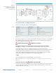
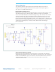
Figure 3.
Active transient suppression
section schematic
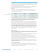
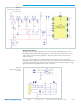
Figure 4.
Output enable control
schematic
Output Enable Control
The EN pin is pulled low to disable the AC-DC converter. If pulled high to 3.3 V or
le floating, the VI Brick® PFM® will operate. A 1x5 0.100” spaced socket allows easy
connection to automated test equipment. This part of the circuit is referenced to
primary ground.
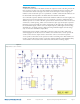
Users can connect their own secondary referenced control circuit by connecting
through the optocoupler U01, and connecting to TP12 and TP11 as needed. JP04 can be
removed to allow a floating reference for the enable input. On this TP12 input, a high
signal will result in shutdown of the AC-DC converter.