Victa Lawnmower Assembly and Owner’s Manual WARNING! Read this manual before operating your VICTA Lawnmower.
IMPORTANT INFORMATION Labels The following warning labels are attached to your mower on purchase. Please read before discarding. 2 Stroke Label Victa 2 Stroke Engine Fuel Oil Ratio 25:1 = 200ml of Oil for 5 Litres of Fuel Victa Formula V 2 Stroke High Performance Motor Oil (fuel oil ratio 50:1) 100ml of Oil to 5 Litres of Unleaded Fuel. PLEASE NOTE 50:1 OIL RATIO IS ONLY WITH APPROVED “VICTA FORMULA V 2 STROKE OIL” 4 Stroke Label Victa V40 Engine Engine must have 600ml off S.A.E.
Table of Contents 1 Important Notes Unit Details 2 Safety & Handling Safety Instructions Hazards Personal Safety Equipment Assembly Procedures 5 Grasscatcher Handle Knobs/Toggles Attaching Handles Mulching Plug Aerogrip Handle Assembly Assembly Procedure Attaching The Remote Air Filter Housing Attaching Battery (Keystart models only) Operating Instructions 16 Mowing & Mulching Tips Starting & Stopping Self Propelled Maintenance & Care 18 Cleaning Blade Replacement Remote Air Filter Maintenance
IMPORTANT NOTES Congratulations on your purchase of a top quality Victa lawnmower. This instruction manual will aid in the assembly, operation and maintenance of your new lawnmower. Please read carefully to ensure safety and the long life of your product. Do not operate the unit before reading this manual. Do not operate before reading the ‘Engine Manual’. Keep this instruction manual in a safe place for future reference or if service is required on your unit.
Safety Instructions Transporting the mower • Turn the engine off, by moving the throttle lever to the 'STOP' position and switching the fuel tap off (where fitted). • Disconnect the spark plug lead and wedge it between the cylinder head fins. • Do not transport the mower in a vehicle if there is fuel in the fuel tank. • Remove the starter key and disconnect the battery (Keystart models only). Before using the mower • Read the separate 4 stroke or 2 stroke engine manual.
Safety Instructions (cont.) • Start the engine carefully with feet well clear of blades. Do not tilt the mower when starting the engine. • Stop the engine whenever you leave the mower, even for a moment. • Mow only in good daylight. • Keep hands and feet away from rotating parts beneath mower when engine is running. • Do not over speed the engine or alter the governor settings. Excessive engine speed is dangerous and shortens mower life. • Never lift, carry or tilt the mower when the engine is running.
Hazards The following safety precautions must be strictly observed to avoid the risk of damage or personal injury. • D o not smoke while operating or refuelling the mower. Never add fuel or remove the fuel cap while the engine is running or hot. If the fuel is spilt, do not start the engine. Move the mower away from the area of the spill. Do not create any source of ignition until the fuel vapours have dissipated. • C heck all fasteners regularly.
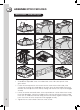
ASSEMBLYPROCEDURES Grasscatcher - hard/solid type 1A (adjustable) type 1B (directional) type Assembling the grasscatcher 1 Assemble the adjustable covers 1A or directional covers 1B to the top half of the grasscatcher 5 2 ocate the centre protrusion of the mesh into the centre hole on the inside of the L catcher top, ensuring the curved edge of the mesh faces the rear handle. Firmly push the mesh into the top half of the catcher, making sure that the four snap hooks engage securely.
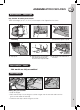
ASSEMBLYPROCEDURES Grasscatcher - fabric type Type Bag Catcher Assembly Instructions There are 6 edges (A, B, C, D, E & F) which require to be clipped into the frame. 1 - Insert metal frame into catcher bag. Catcher Bag. 2 - Clip edge A to frame. 3 - Clip edge B and repeat the 4 - Clip edge C. 5 - Hold the plate in one hand. Then 6 - Clip edge F on the under side of push edge C through the gap. Use this method edges C and E. process for the opposite edge D. the frame.
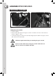
ASSEMBLYPROCEDURES Grasscatcher - 16in model Text Rear flap Fig. 1 Fig. 2 Fitting the grasscatcher • Stop the engine. • Raise the rear flap and hook the grasscatcher on the bar at the rear of the mower as shown in figures 1 and 2. • To remove the grasscatcher, lift the rear flap and grasp the handle on the grasscatcher and unhook from the rear bar. STOP the engine before fitting or removing the grasscatcher.
ASSEMBLYPROCEDURES Handle Knobs/Toggles Mowers will have either knobs or toggles to fix the handles in position. Refer to the instruction below which is specific to your particular model. • Tighten the handle knobs to secure the upper handle to the lower handle. • Flip the handle toggles to secure the upper handle to the lower handle. • On some models the knobs/toggles have to be consumer fitted.
ASSEMBLY PROCEDURES Attaching the lower handles Model All 16in Steel Models **Disconnect spark plug lead first** 1. Fit one of the bolts through the handle hole from the inside and into the square hole in mounting bracket of the base. place washer then spring washer and secure with nut but do not fully tighten at this stage. 2. Repeat the same step for the remaining three securing bolts. 3. Tighten all four nuts securely.
ASSEMBLY PROCEDURES Handle assembly parts (only on self assembled handle) Model All 18in Steel Models Your lawnmower should include a kit with the following parts.
ASSEMBLYPROCEDURES Attaching the lower handles straight and loop Model All 18in Steel Models Nut Painted saddle plate Lower handle **Disconnect spark plug lead first** 1. Place one of the bolts through one of the unpainted saddle plates 2. Whilst holding open the rear catcher flap, insert the bolt and saddle plate through the rear of the mower and up through the small hole in the left hand side of the lawnmower chassis, from underside. Unpainted saddle plate Bolt 3.
ASSEMBLYPROCEDURES Mulching Plug - (mulch or catch models only) • Stop the engine and set the mower height setting. • Mulching is most effective between height settings 4 and 10. • Lift the rear flap and identify the support plate as shown. Note the orientation of the mulching plug. • Insert the mulching plug into the baseplate. • Ensure that the mulching plug is resting on the support plate and is positioned against the inside of the baseplate.
ASSEMBLYPROCEDURES Aerogrip Handle Assembly 1 1 2 3 Your Aerogrip handle may require some assembly before its first use. If the upper and lower handle have been supplied unattached, follow these instructions below. PIVOT JOINT COMPONENTS ITEM QTY 3 4 5 6 4 5 6 1. Lower handles x2 2. Centre knuckle x1 3. Lock nut x2 4. Washer x2 5. Lever x2 6. Upper handles x1 Assembly Procedure 1 L ay the upper handle across the engine cowl of the lawnmower, with the bend facing down (see Fig.
ASSEMBLYPROCEDURES Attaching The Remote Air Filter Housing Aerogrip Handles 2 Stroke Models 4 Stroke Models Aerogrip handle Air filter housing Sc rew Aerogrip handle Nut r Air housing Nut Screw (Pleas e Note: Do not over tighten) Sc rew Throttle control Control F ig. 4 F ig. 3 4 Stroke Models Slide the air filter housing onto the upper handle. Position locating lug into hole in handle and secure with screw (see Fig.3). Be careful not to over tighten, as the plastic thread may be damaged.
ASSEMBLYPROCEDURES Attaching The Remote Air Filter Housing - throttle control Comfort Grip Handles 2 Stroke Models Comfort handle Nut Air filter housing Screw 2 Stroke Models Slide the air filter housing onto the upper handle. Position to locating hole in handle and secure with screw and nut (see Fig.1). Using the 38mm screw and nut pictured here. Fig.
ASSEMBLYPROCEDURES Mulching / Catching 1 2 3 4 Height adjustment allows lawn to be cut at different lengths. • Set cutting height by adjusting the height lever. • For Mulch or Catch models, mulch grass between settings 4 to 10. • A lower setting may be used depending upon conditions. STOP the engine before adjusting the cutting height. Mowing & Mulching Tips • A mulching mower is designed to cut, retain, and recut the clippings until they have reached a very small size.
OPERATING INSTRUCTIONS Starting & Stopping 2 Stroke Engine - See engine manual or Key start procedure below. 4 Stroke Engine - Honda GCV 160, see engine manual & procedure below. 4 Stroke Engine - Briggs & Stratton, see engine manual & procedure below. STEP-1. Move the throttle control lever to the choke/start position. Starting hot: Use the RUN position if the Engine is warm. Note: If engine does not have a choke.
OPERATING INSTRUCTIONS Self Self Propelled Propelled Drive Control operation • To engage drive - press engagement lever against mower handle. • Hold there while drive is required. • To disengage drive - release lever. NOTE: Drive control adjustment is automatic All self propelled models are fitted with a self adjusting mechanism which eliminates the need for any drive control adjustment.
Blade Replacement Model All 19in Steel and Alloy Chassis Models All 18in Steel Chassis Models For Your Safety • Never use the mower unless the grasscatcher or the guards supplied by the manufacturer are in position. • Before starting the mower check blades and bolts for damage or wear. • If you strike an obstruction, stop the engine and check the blades for damage. Worn and damaged blades are major hazards. • Stop the engine and disconnect the spark plug lead before fitting new blades.
Blade Replacement Model All 16in Steel Models For Your Safety • Never use the mower unless the grasscatcher or the guards supplied by the manufacturer are in position. • Before starting the mower check blades and bolts for damage or wear. • If you strike an obstruction, stop the engine and check the blades for damage. Worn and damaged blades are major hazards. DO NOT lay mower on side (4 stroke models).
Remote Air Filter Maintenance For correct engine performance and to guard against dust entering the engine, causing rapid wear, the air filter assembly must be clean and maintained in good condition. VICTA recommends that the air filter element and seal ring are replaced annually, or more often in dusty conditions. Always replace with genuine Victa spare parts. Use of non-genuine spare parts may damage your mower engine, and void the product warranty. Replacing Air Filters Fig. 1 Fig. 2 STOP ENGINE.
Remote Air Filter Maintenance – Aerogrip Handles 1 Examine the air filter hosing for holes, chafing and leaks. Replace it if damaged. Latch Unclip here to remove top 2 Remove the top cover of the air filter housing by squeezing the latch on the underside of the housing and lifting upwards. 3 Remove the element and the foam seal ring, taking care that any loose dirt does not fall into the filter body. 4 D ust off the seal and examine it. Replace it if damaged or permanently crushed.
Keystart Battery Do not disassemble, puncture or incinerate the battery. Do not allow the battery terminals to contact metal or conductive surfaces. This will cause a spark sufficient to ignite fuel vapors which may result in fire and injury. Do not make direct contact between the postive and negative terminals as this will cause a high current flow, creating sparking and/or a possible fire hazard. Reversing the connections will damage the charger, necessitating replacment.
Keystart Battery Handling and Care Like all batteries, these units contain corrosive fluids and toxic materials. Handle the battery with care. • Keep children away from the battery. • The battery should be charged by adults. • Charge the battery in a well ventilated area. • Keep the battery clean. Do not clean with petrochemicals. Dust with a soft brush and ensure that dust does not collect on the battery terminals, recharge socket or inside the protection boot. • Store the battery in a cool dry place.
Maintenance Chart Remote air filter hose Check Cutting system (Blades) Inspect and check assembly Inspect and check assembly Chassis Check for buildup of grass Check Clean • • • • • • • • Replace Engine cylinder fins Clean Spark plug Replace All accessible fasteners Check As required Monthly/80 hrs Refuelling • • Replace Air filter • • • • • • • Retighten Engine mounting bolts • Check and retighten Mulching plug Inspect and check assembly Muffler Inspec
Troubleshooting In small engines generally, difficult starting and erratic running is most often caused by a dirty spark plug. If a new spark plug of the correct type does not restore the engine to proper operating condition, the problem may be solved by reference to the chart below.
WARRANTY Warranty Consumer Rights The buyer should be aware that in relation to goods which are of a kind ordinarily acquired for personal, domestic or household use or consumption, certain provisions such as the Trade Practices Act, 1974 (Aust) and the Consumer Guarantees Act, 1993 (NZ) apply. The terms set out below do not exclude rights and remedies implied by a statute which are non-excludable and which may be more extensive than those provided by this warranty.
WARRANTY Warranty continued Under Express Warranty the Lawnmower is warranted from the date of purchase against mechanical defects and faulty workmanship or material. Express Warranty covers only the replacement, repair or adjustment of parts which fail due to a fault in manufacture. Defective parts will be replaced or serviced by an Authorised Service Centre without charge for labour or materials, subject to conditions.
NOTES 29
NOTES 30
NOTES 31
NOTES 32
©2010 Victa Lawncare Pty Ltd Victa is a trademark of Victa Ltd. Victa Razor & Aerogrip are registered trademarks of Victa Ltd. All rights reserved. No part of this booklet may be reproduced by any means without prior written permission. All information herein is subject to change without notice.