
Installation Guide
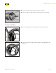

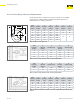

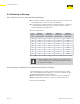

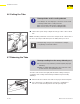
Table Of Contents
- About this Document
- Disclaimer
- Product Information
- Handling Instructions
- Installation Instructions
- Limited Warranty
- ProPress approved applications
- Minimum distance between press fittings
- ProPress standard jaws clearance requirements
- ProPress standard jaws clearance requirements between tube, wall, and floor
- ProPress compact jaws clearance requirements
- ProPress compact jaws clearance requirements between tube, wall, and floor
- ProPress rings dimensions
- ProPress rings with V1 Actuator clearance requirements
- ProPress rings with V2 Actuator clearance requirements
- ProPress rings with V1 Actuator clearance requirements between tube, wall, and floor
- ProPress rings with V2 Actuator clearance requirements between tube, wall, and floor
- ProPress rings with C1 Actuator clearance requirements between tube, wall, and floor
- ProPress XL-C rings dimensions
- ProPress XL-C rings clearance requirements
- ProPress XL-C rings clearance requirements between tube, wall, and floor
- Minimum distance between existing soldered or brazed fitting and ProPress fitting
- Minimum distance between existing ProPress fitting and soldered or brazed fitting
- Minimum insertion depths for ProPress ½" to 2" fittings
- Insertion depths for ProPress ½" to 2" no-stop couplings
- Insertion depths for ProPress ½" to 2" extended no-stop couplings
- Minimum insertion depths ProPress 2½" to 4" fittings
- Insertion depths for ProPress 2½" to 4" no-stop couplings

Installation Instructions
23 of 44
IM-PP 724607 0320 ProPress
4.2 Installing and Mounting the Tube
Observe the general rules of hanging and mounting:
■ Fixed tubing should not be used as support for other tubing and
components.
■ Do not use pipe hooks.
■ Observe distance between ttings and mounting points.
■ Observe the expansion direction – plan xed and sliding mounts.
4.2.1 Pipe Hangers and Supports
Tubing supports perform two functions:
■ To provide support for the tubing.
■ To guide the tube during thermal expansion and contraction.
Fittings must not be used as support
■ System malfunction may result from additional stress and
strain put on the tting.
■ At no point in the system should a tting be the sole means
of support. For example, when installing a tee, both the
branch and the trunk must be properly supported.
Industry standard practices and guidelines shall be used for tube layout
and support. Viega press connections require no special consideration for
support.
Hangers and supports must conform to the local code requirements. In
the absence of local code requirements, hangers and supports should
conform to ANSI/MSS SP 58 Pipe Hangers and Supports - Materials,
Design, Manufacture, Selection, Application and Installation.
4.3 Space Requirements and Intervals
Not enough space
Malfunctions may arise from improper technique.
■ Adhere to minimum space requirements.
■ Make sure that the space required for pressing tools is
available if ttings will be pressed immediately upstream or
downstream from wall or ceiling penetrations.
■ Take the minimum required distances into consideration
during the planning phase of the project whenever possible.