
Installation Guide
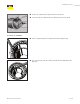

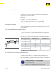
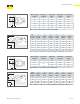
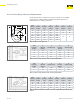

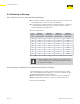

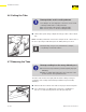
Table Of Contents
- About this Document
- Disclaimer
- Product Information
- Handling Instructions
- Installation Instructions
- Limited Warranty
- ProPress approved applications
- Minimum distance between press fittings
- ProPress standard jaws clearance requirements
- ProPress standard jaws clearance requirements between tube, wall, and floor
- ProPress compact jaws clearance requirements
- ProPress compact jaws clearance requirements between tube, wall, and floor
- ProPress rings dimensions
- ProPress rings with V1 Actuator clearance requirements
- ProPress rings with V2 Actuator clearance requirements
- ProPress rings with V1 Actuator clearance requirements between tube, wall, and floor
- ProPress rings with V2 Actuator clearance requirements between tube, wall, and floor
- ProPress rings with C1 Actuator clearance requirements between tube, wall, and floor
- ProPress XL-C rings dimensions
- ProPress XL-C rings clearance requirements
- ProPress XL-C rings clearance requirements between tube, wall, and floor
- Minimum distance between existing soldered or brazed fitting and ProPress fitting
- Minimum distance between existing ProPress fitting and soldered or brazed fitting
- Minimum insertion depths for ProPress ½" to 2" fittings
- Insertion depths for ProPress ½" to 2" no-stop couplings
- Insertion depths for ProPress ½" to 2" extended no-stop couplings
- Minimum insertion depths ProPress 2½" to 4" fittings
- Insertion depths for ProPress 2½" to 4" no-stop couplings

Installation Instructions
24 of 44
IM-PP 724607 0320 ProPress
4.3.1 Transition Fittings
4.3.1.1 Threaded Connections
The Viega ProPress systems can be joined with o-the-shelf threaded
ttings made of non-ferrous metals.
In this regard:
■ The threaded connection is made rst.
■ The press connection is made second.
This process avoids unnecessary torsion on the press tting.
4.3.1.2 Flange Connections
When using Viega anges, bolt the ange end in place prior to pressing the
tting to the tube.
4.3.2 Minimum Distance between Fittings
To ensure a correct press, a minimum distance between press ttings must
be maintained. Failure to provide this distance may result in an improper seal.
For installations where the minimum distance is zero, it is particularly
important to ensure the correct insertion depth of the tube into each tting.
Tube Diameter (inches) A minimum (inches) A minimum (mm)
½
0 0
¾
1
1¼
7
/
16
10
1½ ⅝ 15
2 ¾ 20
2½
⅝ 153
4
Table 2: Minimum distance between press ttings
minimum
distance
4.3.3 ProPress Jaws Clearance Requirements
The minimum distance between tube, or the tube and the wall/ceiling
construction, must be taken into consideration in the planning phase for a
problem free work process. The following illustrate the clearance requirements
for the jaws and ttings and the procedure for pressing ttings in tight quarters.
Tubing installed too closely together
Connection may leak
■ Adhere to minimum intervals between ttings.
■ Insert tube to full insertion depth before pressing.