
Installation Guide
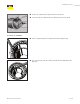

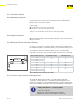
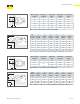
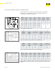

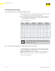

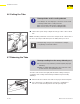
Table Of Contents
- About this Document
- Disclaimer
- Product Information
- Handling Instructions
- Installation Instructions
- Limited Warranty
- ProPress approved applications
- Minimum distance between press fittings
- ProPress standard jaws clearance requirements
- ProPress standard jaws clearance requirements between tube, wall, and floor
- ProPress compact jaws clearance requirements
- ProPress compact jaws clearance requirements between tube, wall, and floor
- ProPress rings dimensions
- ProPress rings with V1 Actuator clearance requirements
- ProPress rings with V2 Actuator clearance requirements
- ProPress rings with V1 Actuator clearance requirements between tube, wall, and floor
- ProPress rings with V2 Actuator clearance requirements between tube, wall, and floor
- ProPress rings with C1 Actuator clearance requirements between tube, wall, and floor
- ProPress XL-C rings dimensions
- ProPress XL-C rings clearance requirements
- ProPress XL-C rings clearance requirements between tube, wall, and floor
- Minimum distance between existing soldered or brazed fitting and ProPress fitting
- Minimum distance between existing ProPress fitting and soldered or brazed fitting
- Minimum insertion depths for ProPress ½" to 2" fittings
- Insertion depths for ProPress ½" to 2" no-stop couplings
- Insertion depths for ProPress ½" to 2" extended no-stop couplings
- Minimum insertion depths ProPress 2½" to 4" fittings
- Insertion depths for ProPress 2½" to 4" no-stop couplings

Installation Instructions
26 of 44
IM-PP 724607 0320 ProPress
4.3.4 ProPress Rings Clearance Requirements
Ensure that the space required for system pressing tools is available
if Viega ProPress ttings will be installed immediately upstream or
downstream from ceiling penetrations.
Tube
Diameter
(inches)
A
minimum
(inches)
A
minimum
(mm)
B
minimum
(inches)
B
minimum
(mm)
C
minimum
(inches)
C
minimum
(mm)
½ 2¼ 57 2⅛ 54 1
1
/
16
27
¾ 2
11
/
16
68 2⅞ 73 1⅛ 28
1 2
15
/
16
75 3
5
/
16
84
1
3
/
16
30
1¼ 3
5
/
16
84 3⅞ 99
1½ 3
11
/
16
94 4
5
/
16
110
2" 4
7
/
16
113 5
7
/
16
139
Table 7: ProPress rings dimensions
Tube
Diameter
(inches)
A
minimum
(inches)
A
minimum (mm)
B
minimum
(inches)
B
minimum (mm)
½ 1⅝ 41 2
3
/
16
71
¾ 1¾ 45 2
3
/
16
55
1 2 51 1⅝ 42
1¼ 2
3
/
16
55 2
15
/
16
75
Table 8: ProPress rings with V1 Actuator clearance requirements
Tube
Diameter
(inches)
A
minimum
(inches)
A
minimum (mm)
B
minimum
(inches)
B
minimum (mm)
1½ 2⅜ 60 3
5
/
16
85
2 2
9
/
16
65 4⅛ 105
Table 9: ProPress rings with V2 Actuator clearance requirements
Tube
Diameter
(inches)
A
minimum
(inches)
A
minimum
(mm)
B
minimum
(inches)
B
minimum
(mm)
C
minimum
(inches)
C
minimum
(mm)
½ 1⅝ 41 3
9
/
16
90 2
5
/
16
59
¾ 1¾ 45 3⅝ 92 2⅛ 55
1 2 51 3
13
/
16
97 2
3
/
16
56
1¼ 2
3
/
16
55 3¾ 92 2⅛ 55
Table 10: ProPress rings with V1 Actuator clearance requirements between tube, wall,
and oor
"
#
$
A
B
C