
Installation Guide


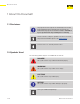


Table Of Contents
- About this Document
- Disclaimer
- Product Information
- Handling Instructions
- Installation Instructions
- Limited Warranty
- ProPress approved applications
- Minimum distance between press fittings
- ProPress standard jaws clearance requirements
- ProPress standard jaws clearance requirements between tube, wall, and floor
- ProPress compact jaws clearance requirements
- ProPress compact jaws clearance requirements between tube, wall, and floor
- ProPress rings dimensions
- ProPress rings with V1 Actuator clearance requirements
- ProPress rings with V2 Actuator clearance requirements
- ProPress rings with V1 Actuator clearance requirements between tube, wall, and floor
- ProPress rings with V2 Actuator clearance requirements between tube, wall, and floor
- ProPress rings with C1 Actuator clearance requirements between tube, wall, and floor
- ProPress XL-C rings dimensions
- ProPress XL-C rings clearance requirements
- ProPress XL-C rings clearance requirements between tube, wall, and floor
- Minimum distance between existing soldered or brazed fitting and ProPress fitting
- Minimum distance between existing ProPress fitting and soldered or brazed fitting
- Minimum insertion depths for ProPress ½" to 2" fittings
- Insertion depths for ProPress ½" to 2" no-stop couplings
- Insertion depths for ProPress ½" to 2" extended no-stop couplings
- Minimum insertion depths ProPress 2½" to 4" fittings
- Insertion depths for ProPress 2½" to 4" no-stop couplings

5 of 44IM-PP 724607 0320 ProPress
Table of Contents
List of Tables
Table 1 ProPress approved applications __________________________ 8
Table 2 Minimum distance between press ttings _________________ 24
Table 3 ProPress standard jaws clearance requirements ___________ 25
Table 4 ProPress standard jaws clearance requirements between
tube, wall, and oor ___________________________________ 25
Table 5 ProPress compact jaws clearance requirements ___________ 25
Table 6 ProPress compact jaws clearance requirements between
tube, wall, and oor ___________________________________ 25
Table 7 ProPress rings dimensions _____________________________ 26
Table 8 ProPress rings with V1 Actuator clearance requirements ____ 26
Table 9 ProPress rings with V2 Actuator clearance requirements ____ 26
Table 10 ProPress rings with V1 Actuator clearance requirements
between tube, wall, and oor ___________________________ 26
Table 11 ProPress rings with V2 Actuator clearance requirements
between tube, wall, and oor ___________________________ 27
Table 12 ProPress rings with C1 Actuator clearance requirements
between tube, wall, and oor ___________________________ 27
Table 13 ProPress XL-C rings dimensions ________________________ 27
Table 14 ProPress XL-C rings clearance requirements ______________ 27
Table 15 ProPress XL-C rings clearance requirements between tube,
wall, and oor ________________________________________ 27
Table 16 Minimum distance between existing soldered or brazed tting
and ProPress tting ___________________________________ 28
Table 17 Minimum distance between existing ProPress tting and soldered
or brazed tting _______________________________________ 29
Table 18 Minimum insertion depths for ProPress ½" to 2" ttings _____ 31
Table 19 Insertion depths for ProPress ½" to 2" no-stop couplings ___ 32
Table 20 Insertion depths for ProPress ½" to 2" extended no-stop
couplings ____________________________________________ 32
Table 21 Minimum insertion depths ProPress 2½" to 4" ttings _______ 35
Table 22 Insertion depths for ProPress 2½" to 4" no-stop couplings __ 35