
Installation Guide

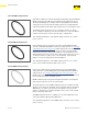


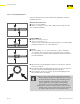
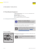
Table Of Contents
- About this Document
- Disclaimer
- Product Information
- Handling Instructions
- Installation Instructions
- Limited Warranty
- ProPress approved applications
- Minimum distance between press fittings
- ProPress standard jaws clearance requirements
- ProPress standard jaws clearance requirements between tube, wall, and floor
- ProPress compact jaws clearance requirements
- ProPress compact jaws clearance requirements between tube, wall, and floor
- ProPress rings dimensions
- ProPress rings with V1 Actuator clearance requirements
- ProPress rings with V2 Actuator clearance requirements
- ProPress rings with V1 Actuator clearance requirements between tube, wall, and floor
- ProPress rings with V2 Actuator clearance requirements between tube, wall, and floor
- ProPress rings with C1 Actuator clearance requirements between tube, wall, and floor
- ProPress XL-C rings dimensions
- ProPress XL-C rings clearance requirements
- ProPress XL-C rings clearance requirements between tube, wall, and floor
- Minimum distance between existing soldered or brazed fitting and ProPress fitting
- Minimum distance between existing ProPress fitting and soldered or brazed fitting
- Minimum insertion depths for ProPress ½" to 2" fittings
- Insertion depths for ProPress ½" to 2" no-stop couplings
- Insertion depths for ProPress ½" to 2" extended no-stop couplings
- Minimum insertion depths ProPress 2½" to 4" fittings
- Insertion depths for ProPress 2½" to 4" no-stop couplings

Product Information
11 of 44
IM-PP 724607 0320 ProPress
1 Each tting contains an application specic sealing element. ProPress
comes from the factory with an EPDM sealing element. This may be
replaced with and FKM or HNBR sealing element depending on the
application.
2 Viega’s distinctive hexagonal pressing pattern bonds the tting and
tube and provides the mechanical strength for the connection.
3 Color coded dots indicate the presence of Viega’s unique Smart
Connect technology which helps installers ensure that they have
pressed all connections.
4 Cylindrical guides ensure the proper insertion of the tube and protects
the sealing element.
1 The 420 stainless steel grip ring's teeth bite into the tube and lock the
tting securely in place.
2 A PBT (Polybutylene Terephthalate) separator ring protects the sealing
element from damage by creating a positive physical separation during
installation and later during pressing.
3 The EPDM sealing element ensures water-tight or air-tight connections.
ProPress 2½" to 4" ttings are designed to be pressed with ProPress XL-C
press rings and V2 actuator to produce a non-detachable, secure connection.
2.4.4 Copper Tubing
Viega ProPress may only be pressed onto copper tube in accordance
with ASTM B88 or B75. When pressing onto B88 copper tube, types K, L,
and M may be used. Tempers O60 and O50, known as “soft copper”, are
limited to nominal sizes ½" to 1 ¼". Temper H58, known as hard copper,
may be used with nominal sizes ½" to 4". When pressing onto B75 copper
tube, the tube dimensions must be in accordance with Viega specications.
Only tempers H58, O60, and O50 may be used with ProPress.
Copper tubing must be free of surface imperfections,
including metal stamped print lines, before a ProPress
tting is installed.
2.4.5 Press Fittings
2.4.5.1 Viega ProPress ½" to 2" Fittings
2.4.5.2 Viega ProPress 2½" to 4" Fittings
When pressing onto B75 copper tube, additional
considerations apply. See Viega ProPress Copper Tube
Compatibility Tech Data.