
Installation Guide


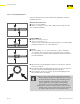
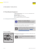
Table Of Contents
- About this Document
- Disclaimer
- Product Information
- Handling Instructions
- Installation Instructions
- Limited Warranty
- ProPress approved applications
- Minimum distance between press fittings
- ProPress standard jaws clearance requirements
- ProPress standard jaws clearance requirements between tube, wall, and floor
- ProPress compact jaws clearance requirements
- ProPress compact jaws clearance requirements between tube, wall, and floor
- ProPress rings dimensions
- ProPress rings with V1 Actuator clearance requirements
- ProPress rings with V2 Actuator clearance requirements
- ProPress rings with V1 Actuator clearance requirements between tube, wall, and floor
- ProPress rings with V2 Actuator clearance requirements between tube, wall, and floor
- ProPress rings with C1 Actuator clearance requirements between tube, wall, and floor
- ProPress XL-C rings dimensions
- ProPress XL-C rings clearance requirements
- ProPress XL-C rings clearance requirements between tube, wall, and floor
- Minimum distance between existing soldered or brazed fitting and ProPress fitting
- Minimum distance between existing ProPress fitting and soldered or brazed fitting
- Minimum insertion depths for ProPress ½" to 2" fittings
- Insertion depths for ProPress ½" to 2" no-stop couplings
- Insertion depths for ProPress ½" to 2" extended no-stop couplings
- Minimum insertion depths ProPress 2½" to 4" fittings
- Insertion depths for ProPress 2½" to 4" no-stop couplings

Product Information
13 of 44
IM-PP 724607 0320 ProPress
2.4.5.7 Fitting Markings
Each ProPress tting is marked with the following:
■ Green dot: EPDM sealing element and Smart Connect technology
■ Size of tting
■ Manufacturer name
■ Manufacturer batch code
■ CSA
®
■ NSF
®
61 and 372
■ UPC
®
■ UL
®
■ FM
Fittings are radially pressed around the sealing element in a single step.
Fittings that do not have cylindrical guides risk making an unsecured
connection. Without the guides, installers may damage the sealing
element.
2.4.5.6 Cylindrical Guides All Viega ttings are designed with cylindrical guides to keep the tube
straight and protect the sealing element during assembly.