
Installation Guide

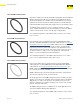


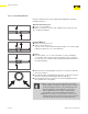
Table Of Contents
- About this Document
- Disclaimer
- Product Information
- Handling Instructions
- Installation Instructions
- Limited Warranty
- ProPress approved applications
- Minimum distance between press fittings
- ProPress standard jaws clearance requirements
- ProPress standard jaws clearance requirements between tube, wall, and floor
- ProPress compact jaws clearance requirements
- ProPress compact jaws clearance requirements between tube, wall, and floor
- ProPress rings dimensions
- ProPress rings with V1 Actuator clearance requirements
- ProPress rings with V2 Actuator clearance requirements
- ProPress rings with V1 Actuator clearance requirements between tube, wall, and floor
- ProPress rings with V2 Actuator clearance requirements between tube, wall, and floor
- ProPress rings with C1 Actuator clearance requirements between tube, wall, and floor
- ProPress XL-C rings dimensions
- ProPress XL-C rings clearance requirements
- ProPress XL-C rings clearance requirements between tube, wall, and floor
- Minimum distance between existing soldered or brazed fitting and ProPress fitting
- Minimum distance between existing ProPress fitting and soldered or brazed fitting
- Minimum insertion depths for ProPress ½" to 2" fittings
- Insertion depths for ProPress ½" to 2" no-stop couplings
- Insertion depths for ProPress ½" to 2" extended no-stop couplings
- Minimum insertion depths ProPress 2½" to 4" fittings
- Insertion depths for ProPress 2½" to 4" no-stop couplings

Product Information
17 of 44
IM-PP 724607 0320 ProPress
2.5.8 Pressure Surges
■ Pressure surges or transients from fast-acting valves, pump surges,
and other sources that result in water hammer may cause damage to
many system components, including press ttings.
■ When fast-acting valves and/or pumps are incorporated into a system,
the designer and installer should isolate press ttings from sharp
pressure surges.
2.5.9 Rotating a Pressed Fitting
Once a ProPress tting has been pressed, it can be rotated (not by hand),
but once rotated more than ve degrees, the tting should be repressed
to restore resistance to rotational movement.
If the tting is re-pressed, care should be taken to align the at sides on
the jaw with those on the tting.
2.5.10 Deection
The pressing process can cause deection (angular misalignment) to
occur. When pressing Viega ProPress ttings in a system, the deformation
of the tting is constant. This allows for a consistent leak-free joint every
time and is a result of the pressing technique.
Deection occurs in the same way for every tting. The tting being
pressed will move in the direction of the jaw or ring opening.
■ Since the tting will deect toward the opening of the jaw or ring, the
tube end will deect in the opposite direction.
■ By counteracting the tting movement, one can minimize the
deection of the tting and ultimately the tube.
■ When using strut and clamps, deection is minimized and nearly
eliminated depending on clamp spacing.
■ ProPress ttings should be isolated or separated by
sucient distance from pumps, fast-acting valves, and
other sources of pressure transients.
■ The maximum operating pressure in a ProPress system
is 200 psi, which applies to general operation as well as
pressure transients.
■ Good engineering practices should be used to design
the system in a way that minimizes sharp pressure
surges.