
Operation Manual


4
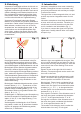
Fig. 3Abb. 3
Fig. 4
90°
Abb. 4
13 mm
Hinter dem Buchstaben eines Ein- oder Ausfahr-
signals steht die Ziffer des Gleises, für welches
das Signal gilt.
Damit Sie Ihre Signale korrekt beschriften können,
liegt dem Signal eine Tafel mit selbstklebenden
Bezeichnungsschildern bei. Schneiden Sie das
gewünschte Schild aus, ziehen Sie die Schutzfo-
lie ab und kleben Sie es auf die Nummerntafel am
Mast des Signals (Abb. 2).
Viele weitere Informationen über Signale nden
Sie im Viessmann-Signalbuch (Art.-Nr. 5299).
3. Funktionskontrolle
Nehmen Sie das Signal vorsichtig aus der Verpa-
ckung. Führen Sie vor der Montage eine Funkti-
onskontrolle durch.
Schließen Sie dazu das gelbe Kabel (ohne Mar-
kierung) an einem Pol eines 16 V-Modellbahn-
transformators (z. B. Viessmann Art.-Nr. 5200) an.
Verbinden Sie abwechselnd jeweils ein blaues Ka-
bel mit dem anderen Pol des Trafos.
Vorsicht:
Niemals die blauen Kabel gleichzeitig anschlie-
ßen. Das kann zur Zerstörung des Signals füh-
ren.
Blau mit roter Markierung:
Signal auf „Halt“ (Hp0), oberer Flügel waagerecht
(wenn vorhanden: unterer Flügel senkrecht)
Blau mit grüner Markierung:
Signal auf „Fahrt“ (Hp1) bzw. „Langsamfahrt“ (Hp2),
oberer Flügel schräg nach oben (wenn vorhanden:
unterer Flügel ebenfalls schräg nach oben)
4. Montage
1. Beschriften Sie das Signal (siehe Kapitel 2).
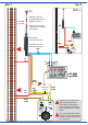
2. Bohren Sie an der Montagestelle ein Loch mit
einem Durchmesser von 13 mm (Abb. 3,
passender Bohrer: Art.-Nr. 7801).
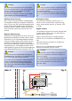
3. Führen Sie die Anschlusskabel von oben durch
das Montageloch und stecken Sie dann das Si-
gnal mit dem Antrieb voran hinein.
3. Checking the function
Remove the signal from the box carefully. Check
all functions prior to installation.
Connect the yellow wire (the one without the resis-
tor) to one of the terminals of a 16 V transformer
(AC/DC) (e. g. Viessmann item-No. 5200). Then
alternately connect each variety of the blue wires
to the other terminal, but only briey.
Caution:
Never connect the blue cables at the same time
to the transformer. This may destroy the signal.
Connecting the cable results in the following arm-
positions:
Blue with red marking:
Signal on “Stop” (Hp0), upper arm horizontal,
(if existing: lower arm vertical).
Blue with green marking:
Signal on “Proceed” (Hp1) or on “Proceed slowly”
(Hp2), upper arm diagonal upwards, (if existing:
lower arm diagonal upwards).
4. Mounting
1. Label your railway signal as described in chap-
ter 2.
2. Drill a mounting hole at the position of your sig-
nal (diameter 13 mm; see g. 3). A convenient
drill is available from Viessmann (item-No.
7801).
3) Insert the signal‘s connection wires into the
hole rst. Then put the signal with the drive rst
into the hole.
4) Attach the signal to the baseboard with the en-
closed ring. Put the ring over the cables and