
Operation Manual


7
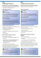
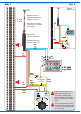
Universal Tasten - Stellpult
5549
Viessmann
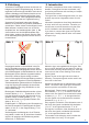
braun
brown
grünrot
braun
brown
blau
rot
red
rot
red
braun
brown
gelb
yellow
z. B. 5549
e. g. 5549
Diode
braun
brown
grün
green
rot
red
braun
brown
blau
blue
rot
red
rot
red
braun
brown
gelb
yellow
z. B. 5549
e. g. 5549
Diode
Widerstand
resistor
Fig. 7
Abb. 7
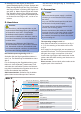
System
Märklin H0
Beachten Sie die
Anschlusshinweise in
Kapitel 6, Seite 5.
Note the connecting
instructions in chapter
6 on page 5.
Dieses Symbol neben dem
Gleis kennzeichnet eine
Trennstelle (Gleichstrom =
rechte Schiene in Fahrtrich-
tung, Wechselstrom = Mittel-
leiter).
This sign beside the track in-
dicates a track insulation (DC
= right rail in driving direction,
AC = third rail).
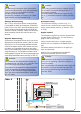
Formsignal
mit einem Antrieb.
Semaphore signal
with one drive unit.
16 V
Universal Tasten - Stellpult
5549
Viessmann
16 V
z. B. 4500
e. g. 4500