Service instructions VIESMANN for contractors Vitocrossal 200 Type CM2 Gas condensing boiler with MatriX radiant burner For applicability, see the last page VITOCROSSAL 200 5692 907 GB 12/2011 Please keep safe.
Safety instructions Safety instructions Please follow these safety instructions closely to prevent accidents and material losses. Safety instructions explained Danger This symbol warns against the risk of injury. ! Please note This symbol warns against the risk of material losses and environmental pollution. Note Details identified by the word "Note" contain additional information.
Safety instructions Safety instructions (cont.) If you smell flue gas Danger Flue gas can lead to life-threatening poisoning. ■ Shut down the heating system. ■ Ventilate the boiler room. ■ Close all doors leading to the living space. Working on the system ■ When using gas as fuel, also close the main gas shut-off valve and safeguard against unauthorised reopening. ■ Isolate the system from the power supply and check that it is no longer 'live', e.g.
Index Index Commissioning, inspection, maintenance Steps – commissioning, inspection and maintenance.......................................... Further details regarding the individual steps....................................................... 5 7 Troubleshooting Diagnosis.............................................................................................................. 40 Start-up problems with 285 kW, open flue operation...........................................
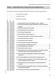
Commissioning, inspection, maintenance Steps – commissioning, inspection and maintenance For further information regarding the individual steps, see the page indicated Commissioning steps Inspection steps Maintenance steps • • 5692 907 GB • • • • • • • • Page 1. Checking the high limit safety cut-out setting............. • • 7 2. Filling the heating system with water and venting the system............................................................................. 7 3.
Commissioning, inspection, maintenance Steps – commissioning, inspection and… (cont.) Commissioning steps Inspection steps Maintenance steps • • • • • 21. Checking the ignition electrodes and ionisation electrode.......................................................................... 24 • • 22. Closing the boiler door.................................................. 25 • • • • • • • 26. Checking the filter element (if fitted) in the gas line and replacing it if required • • 27.
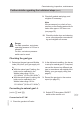
Commissioning, inspection, maintenance Further details regarding the individual steps Checking the high limit safety cut-out setting Never set the high limit safety cut-out higher than 110 °C, set it to a maximum of 110 °C if required. Control unit installation and service instructions Filling the heating system with water and venting the system Record the fill volume, water hardness and pH value on page 29 and 30. Note Observe the "Water quality requirements" on page 62.
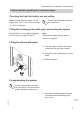
Commissioning, inspection, maintenance Further details regarding the individual steps (cont.) 2. For open flue operation: Check that the vents in the installation room are open. 3. Check the gas supply pressure. 4. Open the gas line shut-off valves. 5. Switch ON the mains isolator (outside the installation room). A B 6. Switch ON system ON/OFF switch B at the control unit.
Commissioning, inspection, maintenance Further details regarding the individual steps (cont.) 9. Check all gaskets and plugs, and retighten if necessary. Note We recommend you check all connections on the heating water side for leaks after approx. 500 hours run (see page 22). 10. Check the boiler door and cleaning cover a few days after commissioning and retighten all screws. Danger For safe operation, a minimum operating pressure of 0.5 bar is essential. For this, a minimum pressure switch can be used.
Commissioning, inspection, maintenance Further details regarding the individual steps (cont.) 03. Switch OFF the mains isolator (outside the installation room) or the power supply and prevent unauthorised reconnection. 09. Secure Venturi mixing pipe H at the gas fan. Connect compensation line E when the boiler is in balanced flue operation. 04. Undo fitting A. 10. Secure fitting A. 11. Affix supplied label "Set to..." F over the existing label. 12. Start the burner (see page 7).
Commissioning, inspection, maintenance Further details regarding the individual steps (cont.) 04. Undo fitting A. 08. Secure the gas train (without restrictor C and without rubber cork gasket D, but including O-ring B) to flange E; replace the factory-fitted M 5 × 16 screws with M 5 × 12 (in the pack). 09. Secure fitting A. 10. Except for 115 kW: Push compensation hose G on to the gas train. 11. Affix supplied label "Set to..." F over the existing label. 12. Start the burner (see page 7).
Commissioning, inspection, maintenance Further details regarding the individual steps (cont.) Checking the static and the supply pressure Static pressure 115 to 311 kW 87 kW A 1. Close the gas shut-off valve. 2. Undo the screw in test nipple A, but do not remove. 3. Connect the pressure tester at test nipple A. 4. Open the gas shut-off valve. 6. Record the actual value in the report (on page 61). 12 5692 907 GB 5. Check the static pressure (max. 60 mbar).
Commissioning, inspection, maintenance Further details regarding the individual steps (cont.) Supply pressure 3. Record the actual value in the report (on page 61). 1. Start the burner. 4. Close the gas shut-off valve. Note For commissioning, see page 7. Switch the burner to maximum heating output. For this, activate the emissions test switch at the control unit. 5. Remove the pressure tester and close test nipple A. 2. Check the supply pressure (flow pressure), see table on page 13.
Commissioning, inspection, maintenance Further details regarding the individual steps (cont.) Checking the CO2 content Preparing the test 1. Open the gas shut-off valve. 2. Start the burner. 3. Press "S" E and "-" D simultaneously. Display C will then show the following: ■ Under Status: "d" (= control stop) ■ Under Service: Modulation level in % ("00." = 100 % = upper heating output, "00" = 0 % = lower heating output) CO2 test at the upper heating output (87 kW) 1.
Commissioning, inspection, maintenance Further details regarding the individual steps (cont.) 3. If the CO2 content must be adjusted: Turn adjusting screw A in small increments until the CO2 content reaches the specified range. ■ Turning clockwise → CO2 content falls ■ Turning anti-clockwise → CO2 content rises Note The adjusting screw has no end-stop. The starting position will be reached again after 4 turns. 4. Record the actual value in the report (on page 61).
Commissioning, inspection, maintenance Further details regarding the individual steps (cont.) 3. If the CO2 content must be adjusted: ■ Remove cover B. ■ Turn adjusting screw A in small increments (Torx 40) until the CO2 content falls within the specified range: – Turning clockwise → CO2 content rises – Turning anti-clockwise → CO2 content falls 4. Record the actual value in the report (on page 61).
Commissioning, inspection, maintenance Further details regarding the individual steps (cont.) 3. If the CO2 content must be adjusted: ■ Remove cap B. ■ Turn setting screw A in small increments (3 mm Allen key) until the CO2 content lies within the specified range: – Turning clockwise → CO2 content falls – Turning anti-clockwise → CO2 content rises 4. Record the actual value in the report (on page 61). CO2 test at the lower heating output (115 kW to 311 kW) 5692 907 GB 1.
Commissioning, inspection, maintenance Further details regarding the individual steps (cont.) 3. If the CO2 content must be adjusted: ■ Remove cover B. ■ Turn adjusting screw A in small increments (Torx 40) until the CO2 content falls within the specified range: – Turning clockwise → CO2 content rises – Turning anti-clockwise → CO2 content falls 4. Record the actual value in the report (on page 61).
Commissioning, inspection, maintenance Further details regarding the individual steps (cont.) Checking the ionisation current A B D C 01. Switch OFF the mains isolator. 07. Switch the mains isolator ON and press reset. 02. Pull ionisation cable plug C. 08. Check the ionisation current. 03. Switch ON the mains isolator. There must be a fault shutdown after the burner has tried to start. Display B flashes fault code "F 25". Note The ionisation current should be at least 3 µA for approx.
Commissioning, inspection, maintenance Further details regarding the individual steps (cont.) Shutting down the system 1. Switch OFF the mains isolator or the power supply and safeguard against unauthorised reconnection. 2. Pull plug-in connector fA and lÖ from the burner. 3. Close the gas shut-off valve. Opening the boiler door 1. Remove the gas supply pipe. 2. Undo the four screws on the boiler door and open the door. ! Please note Scratches inside the combustion chamber can lead to corrosion.
Commissioning, inspection, maintenance Further details regarding the individual steps (cont.) Only use plastic brushes, not wire brushes or sharp objects. For normal cleaning, flush the heating surfaces thoroughly with a water jet. You may use cleaning agents if you notice stubborn residues, surface discolouration or soot deposits. For this, observe the following: ■ Only use solvent-free cleaning agents. Ensure that no cleaning agent gets between the boiler body and the thermal insulation.
Commissioning, inspection, maintenance Further details regarding the individual steps (cont.) Checking all connections on the heating water side and the sensor well for leaks A A Sensor well Note Also check the connections to control equipment and to the minimum pressure switch (low water indicator) for leaks. Cleaning and reconnecting the condensate drain system 5692 907 GB Note Clean the inside of the condensate drain system at least annually.
Commissioning, inspection, maintenance Further details regarding the individual steps (cont.) 1. Pull drain or cleaning hose C off. 2. Clean the inside of the condensate drain system (hose, pipe). 3. Clean the neutralising system (if installed) in accordance with the manufacturer's instructions. Neutralising system operating instructions C B A D Note You can obtain the neutralising agent from Viessmann quoting part no. 9521 702. 4. Release and flush lower part A of siphon B. 5.
Commissioning, inspection, maintenance Further details regarding the individual steps (cont.) Checking the burner gauze assembly 1. Undo fitting A on the gas supply pipe. 2. Undo the screws on the boiler door and open the door. 3. Check the wire mesh of burner gauze assembly B and thermal protection ring C for damage. Slight wavy deformations of burner gauze assembly B are OK. 4. Replace burner gauze assembly B and thermal protection ring C if required.
Commissioning, inspection, maintenance Further details regarding the individual steps (cont.) Closing the boiler door Note Tighten the boiler door screws evenly across with a torque of approx. 18 Nm. Information regarding the door lock Before commissioning, check that the boiler door is seated correctly and has no leaks. If required, correct the alignment of the boiler door by loosening (adjusting) the hinge bracket to ensure there are no leaks. Cleaning the burner 87 kW 2.
Commissioning, inspection, maintenance Further details regarding the individual steps (cont.) Fitting the burner 87 kW 2. Push the connecting cables "100" and "100a" onto the fan. 3. Secure Venturi mixing pipe E with gas train B and gas supply pipe D to fan A. Note For larger burners (246 to 311 kW), the rotary damper is also fitted with a drive at position E. 115 to 311 kW 4. Tighten fitting C on gas supply pipe D. Danger Escaping gas leads to a risk of explosion.
Commissioning, inspection, maintenance Further details regarding the individual steps (cont.) Checking both gas train valves for tightness (for 115 to 311 kW) 4. Connect the pressure tester with the manual pump at test nipple A. 5. Gently activate the manual pump to build a test pressure of approx. 50 mbar. 6. Wait approx.
Commissioning, inspection, maintenance Further details regarding the individual steps (cont.) Checking the gaskets/seals on the flue gas side A D 1. Check flue gas collector C and boiler body A for tightness. 2. Check the lip seal B of the boiler flue connection for tightness. Note The seals/gaskets can also be checked under full load with an inspection mirror. If required, remove the thermal insulation components. Traces of condensate on the outside of flue gas collector C also point towards a leak.
Commissioning, inspection, maintenance Further details regarding the individual steps (cont.) 3. If required, retighten the flue gas collector at clamping clips D. Replace lip seal B if it leaks. Implementing final tests 1. Carry out the final tests according to the notes on page 14 to 19 . 2. Record the actual values in the report (on page 61). Checking the water quality Enter the amount of top-up water, the water hardness and the pH value in the tables. For water quality requirements, see page 62.
Commissioning, inspection, maintenance Further details regarding the individual steps (cont.) Total hardness pH value Feedwater Boiler water Boiler water Water treatment Medium Metering volume Date The pH value should be between 8.2 and 9.5. Checking the diaphragm expansion vessel and system pressure 2. If the pre-charge pressure of the diaphragm expansion vessel is lower than the static system pressure, top up with nitrogen until the pre-charge pressure is 0.1 to 0.2 bar higher. 1.
Commissioning, inspection, maintenance Further details regarding the individual steps (cont.) Checking the mixer for ease of operation and leaks 1. Remove the motorised lever from the mixer handle. 2. Check the mixer for ease of operation. 3. Check the mixer for leaks. Replace the O-ring gaskets if the mixer is leaking. 4. Snap the motorised lever into place. Instructing the system user The installer should instruct the user in the operation of the system. Operating and service documents 1.
Air pressure switch Function The air pressure switch A signal will be interpreted under the following operating conditions: ■ prior to the fan start (idle state check) ■ in the pre-purge phase ■ in control mode, subject to at least a starting output being produced. Any output lower than the starting output is not monitored. Fault shutdown A restart will be initiated 5 times every 2 hours before the burner control unit is set to fault ("L") through a signal from the air pressure switch.
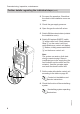
Burner control unit Display and programming unit Function A display and programming unit is integrated into the burner control unit. The display indicates the relevant operating conditions, the service and parameter conditions as well as all fault and error messages. Status Service The display comprises three elements of seven segments each. Four keys enable adjustments to be made at the different operating levels.
Burner control unit (cont.
Burner control unit (cont.
Burner control unit (cont.) DIP switch setting or parameter set The DIP switch (at the back of the display and programming unit) is factory-set to the rated heating output of the burner. A change to this factory setting is only required for operation with reduced heating output. Note If another parameter set is selected, this must be acknowledged (see page 37).
Burner control unit (cont.) Setting Rated burner heating output Parameter set 4 ≙ 246 kW Setting Reduced burner heating output Parameter set 10 ≙ 173 kW ON ON 1 2 3 4 5 6 7 8 1 2 3 4 5 6 7 8 Parameter set 5 ≙ 311 kW Parameter set 11 ≙ 218 kW ON ON 1 2 3 4 5 6 7 8 1 2 3 4 5 6 7 8 Acknowledging a parameter set A flashing "P" is shown under "Status" if a parameter set is changed via the DIP switch or if the burner control unit has been replaced.
Burner control unit (cont.) 3. Press the reset button. The operating display will then be shown again. Displaying the selected parameter set This display will be terminated if no key is pressed within 20 s. Status Service 1. Simultaneously press keys S and a. Status Service 2. Press S. The selected parameter set is displayed under "Service". 3. Simultaneously press keys S and a. The operating display will then be shown again.
Burner control unit (cont.) 2. Press b. The additional fault information will be displayed under "Service" for as long as this key is held down. 3. Press the reset button. The operating display will then be shown again. Fault memory The most recent six faults are saved and may be called up. The order of scans ranges from the most recent to the earlier fault codes. The fault memory display will be terminated if no key is pressed within 20 s. Status Service 1. Press the reset button and a simultaneously.
Troubleshooting Diagnosis Faults with fault indicator on the display and programming unit Message codes Message code A A F System characteris- Cause tics Burner off Gas pressure switch fault Burner off Lack of gas Measures Check the gas pressure switch Notify your gas supply utility See fault code steps See fault code L Burner is in a fault state Air pressure switch switches off during operation P System off Incorrect parameter set selected Check condensate drain, remove flue gas back pressure, re
Troubleshooting Diagnosis (cont.
Troubleshooting Diagnosis (cont.
Troubleshooting Diagnosis (cont.
Troubleshooting Diagnosis (cont.
Troubleshooting Diagnosis (cont.
Troubleshooting Start-up problems with 285 kW, open flue operation Application information Applies only to the MatriX radiant burner, type VMA III with 285 kW, for open flue operation. If the following problems are experienced with the burner: ■ Loud and irregular start-up characteristics. ■ Frequent fault shutdowns with fault message F25 or F27. Modifying the burner settings A B 1. Pull compensation line A. 5692 907 GB 2. Set servomotor control cam B stage 2 to 35°. 3.
5692 907 GB Input = OFF = ON Input Output Output Output Input Output Gas pressure switch Fan Relay Air pressure switch Safety valve Y1 Choke valve Y2 (optional) Ignition/ solenoid valve/ servomotor Flame signal Phase Control Input thermostat Safety Input temperature limiter Fan 100% Output Ignition setting = ON or OFF 19 = ON, if speed is min.
Burner control unit flow chart Burner control unit flow chart (cont.
Burner control unit connection diagram 5692 907 GB Burner control unit connection diagram A Burner control unit MPA 51 B Vitotronic control unit C Fan motor with PWM control and feedback D Flame monitoring via an ionisation current E Display unit with reset function F Air pressure switch G Minimum pressure, gas pressure switch H Ignition unit K Gas fuel safety valve L Choke valve (for 87, 142 and 186 kW) M Servomotor for rotary valve damper (for 246 and 311 kW) 49
Burner control unit connection diagram Burner control unit connection diagram (cont.
Component overview Component overview 5692 907 GB Pressure-jet gas burner, type VMA III, 87 kW A Boiler door B Air pressure switch C Fan D Display and programming unit 51
Component overview Component overview (cont.
Component overview Component overview (cont.
Component overview Component overview (cont.) E F G H I K L Gas train Gas supply pipe Gas shut-off valve Burner gauze assembly Ignition electrodes Ionisation electrode Thermal insulation block M N P Q Burner control unit Ignition unit Suppressor choke box Inlet adaptor for balanced flue operation (for 115, 142 and 186 kW) R Venturi mixing pipe 5692 907 GB Not shown: Choke valve for 142 and 186 kW and rotary valve damper for 246 and 311 kW.
Control unit Adjusting codes at the control unit Vitotronic service instructions In conjunction with the following control units: ■ Vitotronic 100, type GC1B ■ Vitotronic 200, type GW1B ■ Vitotronic 300, type GW2B Rated heating output of the MatriX radiant burner in kW Coding 87 115 142 186 246 311 card 2 2 2 2 2 2 1041 0 0 0 0 0 0 80 5 30 70 25 85 0 1 1 1 2 2 20 20 20 20 20 20 33 33 33 25 33 33 5692 907 GB Coding address 02 05 08 09 15 0A 55
Parts lists Parts lists 001 003 004 101 102 104 105 106 108 109 112 113 114 115 116 117 118 119 120 121 122 123 124 125 126 56 Flue gas collector Siphon Hinge bracket Boiler door Boiler door thermal insulation parts Fixing parts Burner gauze assembly Graphite gasket Ignition unit Ignition cable Ionisation cable Burner control unit Display and programming unit for burner control unit Cable entry for burner control unit Cable harness (servomotor, fan and ignition transformer) for 246 and 311 kW Ignition u
Parts lists Parts lists (cont.) 133 Enriching nozzle 134 Compensation set (only for 115 and 246 kW) 300 Thermal insulation pack 301 Spray paint, Vitosilver 302 Touch-up paint stick, Vitosilver 303 Installation instructions 304 Service instructions A MatriX burner type plate B Label "Set to ..." C Burner cable (see parts list in the service instructions of the boiler control unit) D Boiler control unit (see parts list in the service instructions of the boiler control unit) E Type plate, either on the l.h.
Parts lists Parts lists (cont.
Parts lists Parts lists (cont.
Parts lists Parts lists (cont.
Report Report Setting and test values Static pressure Supply pressure (flow pressure) = for natural gas E = for natural gas LL Tick gas type Carbon dioxide content CO2 ■ at the upper rated actual heating output set ■ at the lower rated actual heating output set Oxygen content O2 ■ at the upper rated actual heating output set ■ at the lower rated actual heating output set Carbon monoxide actual content CO set Commissioning mbar mbar mbar % by vol. % by vol. % by vol. % by vol. % by vol. % by vol.
Water quality requirements Note Observing the following requirements is necessary to safeguard your warranty rights. The manufacturer's warranty excludes damage due to corrosion and scaling. Prevention of damage due to scaling Prevent excessive scale build-up (calcium carbonate) on the heating surfaces.
Water quality requirements (cont.) ■ In systems > 50 kW, install a water meter to record the volume of the fill & top-up water. Enter the volume of the fill water and the water hardness into the boiler maintenance checklists. ■ For systems with a specific system volume in excess of 20 l/kW heating output (apply the output of the smallest boiler in multi boiler systems), apply the requirements of the next highest category of total output (in accordance with the table).
Water quality requirements (cont.) Prevention of damage due to corrosion on the water side Sealed unvented systems– e.g. those equipped with a diaphragm expansion vessel– offer good protection against the ingress of airborne oxygen into the system, if correctly sized and operating at the correct pressure. At every part of the heating system, even at the suction side of the pump and under all operating conditions, the system pressure should be above ambient atmospheric pressure.
Water quality requirements (cont.) 5692 907 GB Where chemicals are used as part of the corrosion protection, we recommend that the manufacturer of the chemicals issues a certificate of suitability of the additives with regard to the boiler materials and the materials of the other heating system components. We recommend you refer questions regarding water treatment to an appropriate specialist. Further details can be found in VDI Directive 2035-2 and EN 14868.
Specification Gas boiler, category I2ELL Rated heating output TV/TR = 50/30 °C kW TV/TR = 80/60 °C kW Rated heat input kW Product ID Connection values*1 relative to the max. load with ■ Natural gas E m3/h 2987 2780 2782 38115 35105 36108 2.83.88.7 11.5 ■ Natural gas LL 3.34.4m3/h 10.1 13.3 Product parameters (according to EnEV) Efficiency η at ■ 100 % of rated % 97.2 97.4 heating output ■ 30 % of rated heat- % 107.9 108.0 ing output Standby loss qB,70 % 0.6 0.
Specification Specification (cont.
Specification Specification (cont.) Gas restrictor dimensions (natural gas E) for 115 to 311 kW a Rated heating output 115 kW 142 kW 186 kW 246 kW 311 kW Dimension a mm 12.9 12.9 16.0 15.7 16.
Certificates Declaration of Conformity We, Viessmann Werke GmbH&Co KG, D-35107 Allendorf, declare as sole responsible body, that the product Vitocrossal 200, type CM2, 87 to 311 (80 to 285) kW with Vitotronic boiler control unit and MatriX radiant burner conforms to the following standards: DIN EN 303 DIN EN 676 DIN EN 15417 DIN EN 15420 DIN EN 50090-2-2 DIN EN 55014-1 DIN EN 55014-2 DIN EN 60335-1 DIN EN 60335-2-102 DIN EN 61000-3-2 DIN EN 61000-3-3 DIN EN 62233 TRD 702 In accordance with the following
Certificates Manufacturer’s certificate according to the 1st BImSchV We, Viessmann Werke GmbH&Co KG, D-35107 Allendorf, confirm that the product Vitocrossal 200, type CM2, 87 to 311 (80 to 285) kW with MatriX radiant burner complies with the following conditions stipulated by the first German Immissions Order (BImSchV): ■ NOx limits in accordance with para. 6 (1). ■ Flue gas loss of max. 9 % in accordance with § 10 (1). Allendorf, 07 December 2010 Viessmann Werke GmbH&Co KG 5692 907 GB pp.
Keyword index Keyword index A Acknowledging a parameter set.........37 Air pressure switch.............................32 Faults without fault display.................45 Flow chart..........................................47 Flow pressure....................................13 B Burner ■ Cleaning.........................................25 ■ Fitting..............................................26 Burner control unit..............................33 Burner gauze assembly, checking.....
Viessmann Werke GmbH&Co KG D-35107 Allendorf Telephone: +49 6452 70-0 Fax: +49 6452 70-2780 www.viessmann.com 72 7247422 7185861 7185865 7247423 7185862 7185866 Viessmann Limited Hortonwood 30, Telford Shropshire, TF1 7YP, GB Telephone: +44 1952 675000 Fax: +44 1952 675040 E-mail: info-uk@viessmann.com chlorine-free bleached paper Printed on environmentally friendly, 7247421 7247425 7185864 Subject to technical modifications. Serial No.